DTC P0234/34 Turbocharger / Supercharger Overboost Condition |
DTC P0299/34 Turbocharger / Supercharger Underboost |
DTC P1251/34 Step Motor for Turbocharger Control Circuit (Intermittent) |
| DTC No. | DTC Detection Condition | Trouble Area |
| P0234/34 | When turbocharger boost pressure continues to be higher than ECM's target boost pressure. (1 trip detection logic) |
|
| P0299/34 | When turbocharger boost pressure continues to be lower than ECM's target boost pressure. (1 trip detection logic) |
|
| P1251/34 | When turbocharger boost pressure is higher than boost pressure for a short time in which there was possibility of engine damage. (1 trip detection logic) |
|
| 1.CHECK OTHER DTC OUTPUT (IN ADDITION TO DTC P0234/34, P0299/34 AND /OR P1251/34) |
Connect the intelligent tester to the DLC3.
Turn the ignition switch ON and turn the intelligent tester ON.
Enter the following menus: Powertrain / Engine / DTC.
Read the DTCs.
| Display (DTC Output) | Proceed to |
| P0234/34, P0299/34 and/or P1251/34 | A |
| P0234/34, P0299/34 and/or P1251/34 and other DTCs | B |
|
| ||||
| A | |
| 2.READ DATA LIST (MAP) |
Connect the intelligent tester to the DLC3.
Start the engine and warm it up. Turn the intelligent tester ON.
Enter the following menu: Powertrain / Engine / Data List / MAP.
| Item | Engine Speed* | Reference Value |
| MAP | Ignition switch ON | Same as atmospheric pressure |
| MAP | Idling | 95 to 105 kPa (713 to 788 mmHg, 28.1 to 31 in.Hg) |
| MAP | 3,000 rpm (no engine load) | 110 to 135 kPa (825 to 1,012 mm Hg, 32.5 to 39.9 in.Hg) |
|
| ||||
| OK | |
| 3.CHECK EXHAUST SYSTEM |
Turn the ignition switch ON.
Check the exhaust pipe for leaks.
|
| ||||
| OK | |
| 4.CHECK AIR CLEANER FILTER |
Check that the air cleaner filter is not clogged.
|
| ||||
| OK | |
| 5.CHECK INTAKE SYSTEM |
Disconnect the air cleaner hose.
Use a mirror to visually check the turbocharger for any mechanical problems.
When the engine is cold, check that the impeller of the turbocharger rotates smoothly, and perform a contact check to confirm whether there is any damage on it.
|
| ||||
| OK | |
| 6.INSPECT TURBOCHARGER SUB-ASSEMBLY |
Disconnect the air cleaner hose.
Use a mirror to visually check the turbocharger for any mechanical problems.
When the engine is cold, check that the impeller of the turbocharger rotates smoothly, and perform a contact check to confirm whether there is any damage on it.
|
| ||||
| OK | |
| 7.CHECK ECM (VNTI VOLTAGE) |
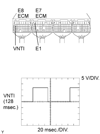 |
While idling the engine, check the waveform of the ECM connectors using an oscilloscope.
| Tester Connection | Specified Condition |
| E8-17 (VNTI) - E7-7 (E1) | Correct waveform is shown |
|
| ||||
| OK | |
| 8.CHECK ECM (VNTO VOLTAGE) |
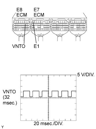 |
While idling the engine, check the waveform of the ECM connectors using an oscilloscope.
| Tester Connection | Specified Condition |
| E8-10 (VNTO) - E7-7 (E1) | Correct waveform is shown |
|
| ||||
| OK | |
| 9.CHECK EGR VALVE ASSEMBLY |
|
| ||||
| OK | |
| 10.INSPECT INTAKE AIR TEMPERATURE SENSOR |
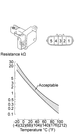 |
Check the IAT sensor.
Remove the MAF meter.
Measure the resistance of the sensor.
| Tester Connection | Condition | Specified Condition |
| 4 - 5 | -20°C (-4°F) | 13.6 to 18.4 kΩ |
| 4 - 5 | 20°C (68°F) | 2.21 to 2.69 kΩ |
| 4 - 5 | 60°C (140°F) | 0.49 to 0.67 kΩ |
|
| ||||
| OK | ||
| ||
