DTC P0327 Knock Sensor 1 Circuit Low Input (Bank 1 or Single Sensor) |
DTC P0328 Knock Sensor 1 Circuit High Input (Bank 1 or Single Sensor) |
DTC P0332 Knock Sensor 2 Circuit Low Input (Bank 2) |
DTC P0333 Knock Sensor 2 Circuit High Input (Bank 2) |
| DTC No. | DTC Detection Condition | Trouble Area |
| P0327 P0332 | Output voltage of knock sensor 1 or 2 is 0.5 V or less (1 trip detection logic) |
|
| P0328 P0333 | Output voltage of knock sensor 1 or 2 is 4.5 V or more (1 trip detection logic) |
|
| Item | Content |
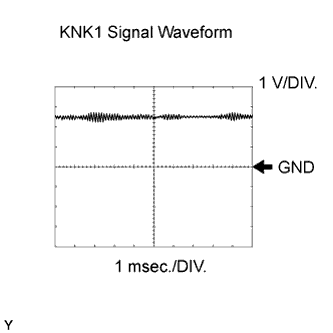
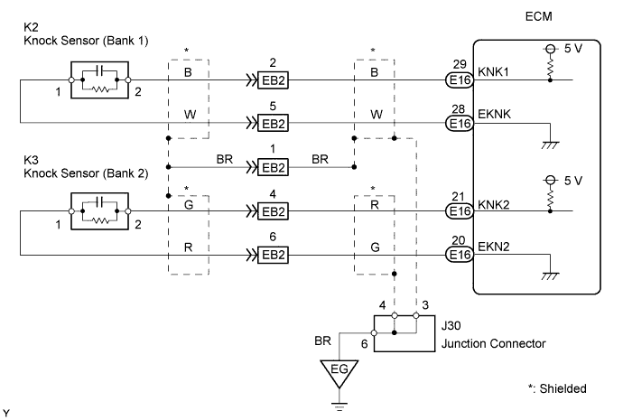
| Symbols (Terminal No.) | KNK1 (E16-29) - EKNK (E16-28) KNK2 (E16-21) - EKN2 (E16-20) |
| Tool Setting | 0.01 to 10 V/DIV., 0.01 to 10 msec./DIV. |
| Condition | Engine speed maintained at 4,000 rpm after warming up engine |
| 1.READ OUTPUT DTC (CHECK KNOCK SENSOR CIRCUIT) |
 |
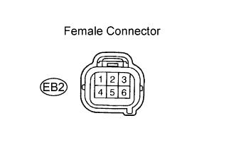
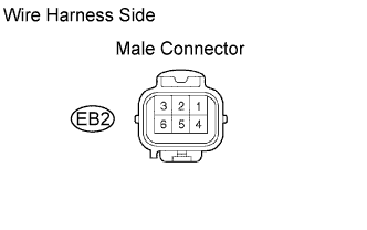
Disconnect the EB2 connector.
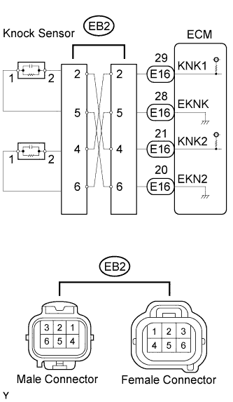
Using lead wires, connect the EB2 connectors as follows.
| Male Connector - Female Connector |
| Terminal 2 - Terminal 4 |
| Terminal 5 - Terminal 6 |
| Terminal 4 - Terminal 2 |
| Terminal 6 - Terminal 5 |
Warm up the engine.
Race the engine at 3,000 rpm for 10 seconds or more.
Check for DTCs.
| Display | Proceed to |
| DTC is same as when vehicle brought in (for example, P0327 and P0328 are output again, or P0332 and P0333 are output again) | A |
| DTC is different from when vehicle brought in (for example, P0327 and P0328 are output at first, but then P0332 and P0333 are output, or vice versa) | B |
|
| ||||
| A | |
| 2.CHECK WIRE HARNESS (EB2 CONNECTOR - ECM) |
 |
Disconnect the EB2 connector.
Disconnect the E16 ECM connector.
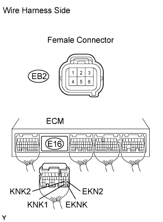
Measure the resistance of the wire harness side connectors.
| Tester Connection | Specified Condition |
| EB2 female connector 2 - E16-29 (KNK1) | Below 1 Ω |
| EB2 female connector 5 - E16-28 (EKNK) | Below 1 Ω |
| EB2 female connector 4 - E16-21 (KNK2) | Below 1 Ω |
| EB2 female connector 6 - E16-20 (EKN2) | Below 1 Ω |
| EB2 female connector 2 or E16-29 (KNK1) - Body ground | 10 kΩ or higher |
| EB2 female connector 5 or E16-28 (EKNK) - Body ground | 10 kΩ or higher |
| EB2 female connector 4 or E16-21 (KNK2) - Body ground | 10 kΩ or higher |
| EB2 female connector 6 or E16-20 (EKN2) - Body ground | 10 kΩ or higher |
|
| ||||
| OK | |
| 3.INSPECT ECM (KNK1, KNK2 VOLTAGE) |
 |
Disconnect the EB2 ECM connector.
Turn the ignition switch ON.
Measure the voltage of the EB2 female connector.
| Tester Connection | Specified Condition |
| EB2 female connector 2 - EB2 female connector 5 | 4.5 to 5.5 V |
| EB2 female connector 4 - EB2 female connector 6 | 4.5 to 5.5 V |
|
| ||||
| OK | |
| 4.CHECK FOR INTERMITTENT PROBLEMS |
| NEXT | ||
| ||
| 5.INSPECT KNOCK SENSOR |
 |
Disconnect the EB2 connector.
Measure the resistance of the EB2 male connector.
| Tester Connection | Specified Condition |
| EB2 male connector 2 - 5 | 120 to 280 kΩ |
| EB2 male connector 4 - 6 | 120 to 280 kΩ |
|
| ||||
| NG | |
| 6.CHECK WIRE HARNESS (EB2 CONNECTOR - KNOCK SENSOR) |
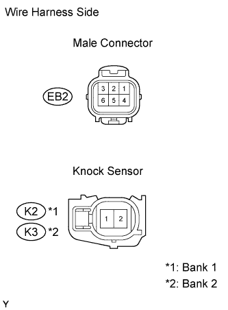 |
Disconnect the EB2 connector.
Disconnect the K2 and K3 knock sensor connectors.
Measure the resistance of the wire harness side connectors.
| Terminal No. | Specified Condition |
| EB2 male connector 2 - K2-2 | Below 1 Ω |
| EB2 male connector 5 - K2-1 | Below 1 Ω |
| EB2 male connector 4 - K3-2 | Below 1 Ω |
| EB2 male connector 6 - K3-1 | Below 1 Ω |
| EB2 male connector 2 or K2-2 - Body ground | 10 kΩ or higher |
| EB2 male connector 5 or K2-1 - Body ground | 10 kΩ or higher |
| EB2 male connector 4 or K3-2 - Body ground | 10 kΩ or higher |
| EB2 male connector 6 or K3-1 - Body ground | 10 kΩ or higher |
|
| ||||
| OK | ||
| ||
