DTC P2238 Oxygen (A/F) Sensor Pumping Current Circuit Low (Bank 1 Sensor 1) |
DTC P2239 Oxygen (A/F) Sensor Pumping Current Circuit High (Bank 1 Sensor 1) |
DTC P2241 Oxygen (A/F) Sensor Pumping Current Circuit Low (Bank 2 Sensor 1) |
DTC P2242 Oxygen (A/F) Sensor Pumping Current Circuit High (Bank 2 Sensor 1) |
DTC P2252 Oxygen (A/F) Sensor Reference Ground Circuit Low (Bank 1 Sensor 1) |
DTC P2253 Oxygen (A/F) Sensor Reference Ground Circuit High (Bank 1 Sensor 1) |
DTC P2255 Oxygen (A/F) Sensor Reference Ground Circuit Low (Bank 2 Sensor 1) |
DTC P2256 Oxygen (A/F) Sensor Reference Ground Circuit High (Bank 2 Sensor 1) |
| DTC No. | DTC Detection Condition | Trouble Area |
| P2238 P2241 | A/F sensor circuit low (bank 1 sensor 1) |
|
| Condition (a) continues for 5.0 sec. or more: (a) AF+ voltage is 0.5 V or less |
| |
| Condition (a) continues for 5.0 sec. or more: (b) (AF+) - (AF-) = 0.1 V or less | ||
| P2239 P2242 | A/F sensor circuit high (bank 1 sensor 1) (2 trip detection logic) |
|
| Condition (a) continues for 5.0 sec. or more: AF+ voltage is greater than 4.5 V |
| |
| Condition (a) continues for 5.0 sec. or more: (b) (AF+) - (AF-) = greater than 0.8 V | ||
| P2252 P2255 | Condition (a) continues for 5.0 sec. or more: AF- voltage is 0.5 V or less (2 trip detection logic) |
|
| P2253 P2256 | Condition (a) continues for 5.0 sec. or more: AF- voltage is greater than 4.5 V |
| Tester Display (Sensor) | Injection Volume | Status | Voltage |
| AFS B1S1 or AFS B2S1 (A/F) | +25% | Rich | Less than 3.0 |
| AFS B1S1 or AFS B2S1 (A/F) | -12.5% | Lean | More than 3.35 |
| O2S B1S2 or O2S B2S2 (heated oxygen sensor) | +25% | Rich | More than 0.55 |
| O2S B1S2 or O2S B2S2 (heated oxygen sensor) | -12.5% | Lean | Less than 0.4 |
| Case | A/F Sensor (Sensor 1) Output Voltage | Heated Oxygen Sensor (Sensor 2) Output Voltage | Main Suspected Trouble Areas | ||
| 1 | Injection volume +25% -12.5% |  | Injection volume +25% -12.5% | | - |
| Output voltage More than 3.35 V Less than 3.0 V | 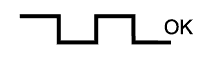 | Output voltage More than 0.55 V Less than 0.4 V |  | ||
| 2 | Injection volume +25% -12.5% | | Injection volume +25% -12.5% | |
|
| Output voltage Almost no reaction |  | Output voltage More than 0.55 V Less than 0.4 V | | ||
| 3 | Injection volume +25% -12.5% | | Injection volume +25% -12.5% | |
|
| Output voltage More than 3.35 V Less than 3.0 V | | Output voltage Almost no reaction | | ||
| 4 | Injection volume +25% -12.5% | | Injection volume +25% -12.5% | |
|
| Output voltage Almost no reaction | | Output voltage Almost no reaction | | ||
| 1.INSPECT AIR FUEL RATIO SENSOR (HEATER RESISTANCE) |
 |
Disconnect the A/F sensor connector.
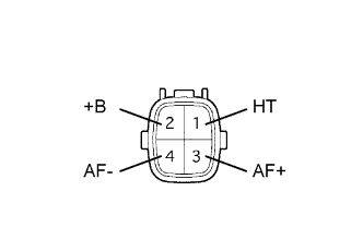
Measure the resistance of the A/F sensor.
| Tester Connection | Condition | Specified Condition |
| 1 (HT) - 2 (+B) | 20°C (68°F) | 1.8 to 3.4 Ω |
| 1 (HT) - 4 (AF-) | - | 10 kΩ or higher |
|
| ||||
| OK | |
| 2.INSPECT RELAY (Marking: A/F) |
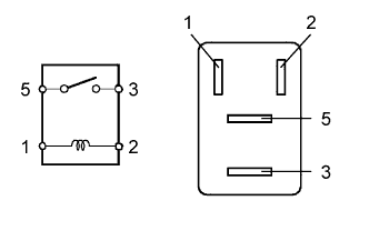 |
Remove the A/F sensor heater relay from the engine room relay block.
Measure the resistance of the relay.
| Tester Connection | Specified Condition |
| 3 - 5 | 10 kΩ or higher |
| 3 - 5 | Below 1 Ω (when battery voltage is applied to terminals 1 and 2) |
|
| ||||
| OK | |
| 3.CHECK WIRE HARNESS (A/F SENSOR - ECM) |
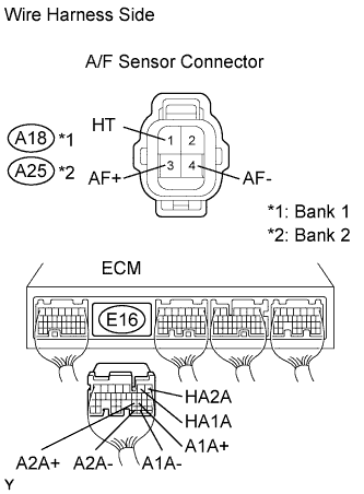  |
Disconnect the A18 or A25 A/F sensor connector.
Disconnect the E6 ECM connector.
Measure the resistance of the wire harness side connectors.
| Tester Connection | Specified Condition |
| A18-1 (HT) - E16-2 (HA1A) | Below 1 Ω |
| A18-3 (AF+) - E16-22 (A1A+) | Below 1 Ω |
| A18-4 (AF-) - E16-30 (A1A-) | Below 1 Ω |
| A25-1 (HT) - E16-1 (HA2A) | Below 1 Ω |
| A25-3 (AF+) - E16-23 (A2A+) | Below 1 Ω |
| A25-4 (AF-) - E16-31 (A2A-) | Below 1 Ω |
| A18-1 (HT) or E16-2 (HA1A) - Body ground | 10 kΩ or higher |
| A18-3 (AF+) or E16-22 (A1A+) - Body ground | 10 kΩ or higher |
| A18-4 (AF-) or E16-30 (A1A-) - Body ground | 10 kΩ or higher |
| A25-1 (HT) or E16-1 (HA2A) - Body ground | 10 kΩ or higher |
| A25-3 (AF+) or E16-23 (A2A+) - Body ground | 10 kΩ or higher |
| A25-4 (AF-) or E16-31 (A2A-) - Body ground | 10 kΩ or higher |
|
| ||||
| OK | ||
| ||
