DTC P0351 Ignition Coil "A" Primary / Secondary Circuit |
DTC P0352 Ignition Coil "B" Primary / Secondary Circuit |
DTC P0353 Ignition Coil "C" Primary / Secondary Circuit |
DTC P0354 Ignition Coil "D" Primary / Secondary Circuit |
DTC P0355 Ignition Coil "E" Primary / Secondary Circuit |
DTC P0356 Ignition Coil "F" Primary / Secondary Circuit |
| DTC No. | DTC Detection Condition | Trouble Area |
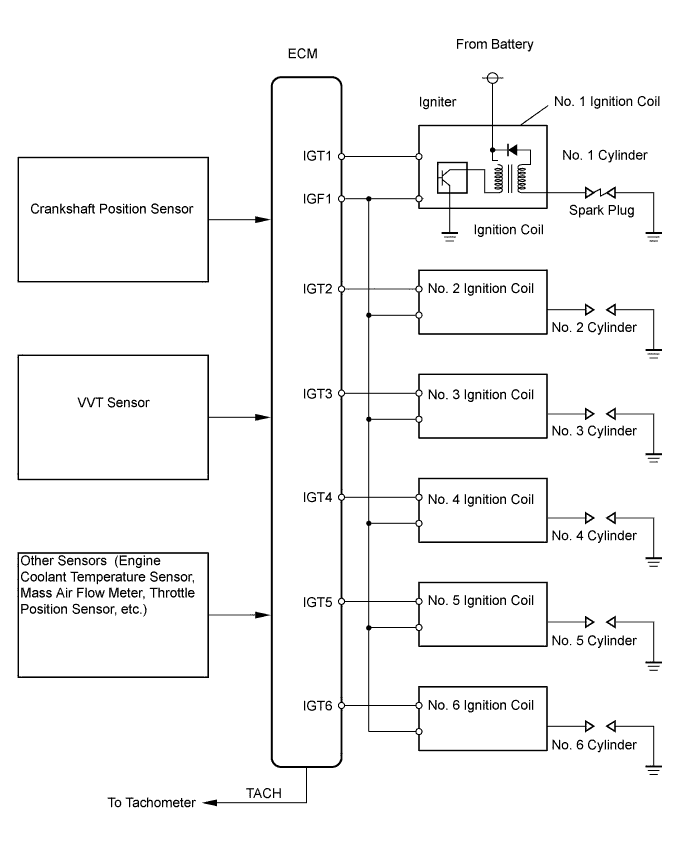
| P0351 P0352 P0353 P0354 P0355 P0356 | No IGF signal to ECM while engine is running (1 trip detection logic) |
|
| Item | Content |
| Symbols (Terminal No.) | IGT1 (E15-8) - E1(E17-1) IGT2 (E15-9) - E1(E17-1) IGT3 (E15-10) - E1(E17-1) IGT4 (E15-11) - E1(E17-1) IGT5 (E15-12) - E1(E17-1) IGT6 (E15-13) - E1(E17-1) IGF1 (E15-24) - E1 (E17-1) |
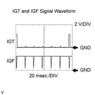
| Tool Setting | 2 V/DIV., 20 msec./DIV. |
| Condition | Idling |
| 1.CHECK SPARK PLUG AND SPARK OF MISFIRING CYLINDER |
|
| ||||
| OK | |
| 2.CHECK WIRE HARNESS (IGNITION COIL ASSEMBLY - ECM (IGF SIGNAL TERMINAL)) |
 |
Disconnect the I7, I8, I9, I10, I11 or I12 ignition coil connector.
Disconnect the E15 ECM connector.
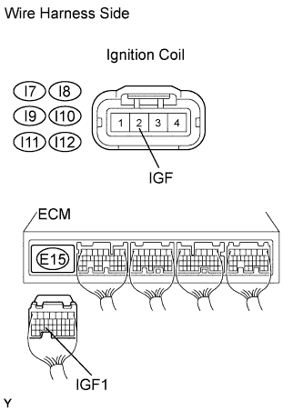
Measure the resistance of the wire harness side connectors.
| Tester Connection | Specified Condition |
| I7-2 (IGF) - E15-24 (IGF1) | Below 1 Ω |
| I8-2 (IGF) - E15-24 (IGF1) | Below 1 Ω |
| I9-2 (IGF) - E15-24 (IGF1) | Below 1 Ω |
| I10-2 (IGF) - E15-24 (IGF1) | Below 1 Ω |
| I11-2 (IGF) - E15-24 (IGF1) | Below 1 Ω |
| I12-2 (IGF) - E15-24 (IGF1) | Below 1 Ω |
| I7-2 (IGF) or E15-24 (IGF1) - Body ground | 10 kΩ or higher |
| I8-2 (IGF) or E15-24 (IGF1) - Body ground | 10 kΩ or higher |
| I9-2 (IGF) or E15-24 (IGF1) - Body ground | 10 kΩ or higher |
| I10-2 (IGF) or E15-24 (IGF1) - Body ground | 10 kΩ or higher |
| I11-2 (IGF) or E15-24 (IGF1) - Body ground | 10 kΩ or higher |
| I12-2 (IGF) or E15-24 (IGF1) - Body ground | 10 kΩ or higher |
|
| ||||
| OK | |
| 3.INSPECT ECM (IGF1 VOLTAGE) |
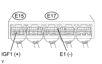 |
Disconnect the ignition coil connector.
Turn the ignition switch ON.
Measure the voltage of the E15 and E17 ECM connectors.
| Tester Connection | Specified Condition |
| E15-24 (IGF1) - E17-1 (E1) | 4.5 to 5.5 V |
|
| ||||
| OK | ||
| ||
| 4.CHECK WIRE HARNESS (IGNITION COIL ASSEMBLY - ECM (IGT SIGNAL TERMINAL)) |
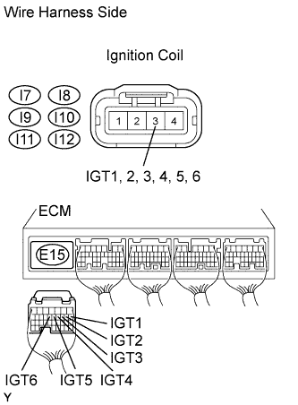 |
Disconnect the I7, I8, I9, I10, I11 or I12 ignition coil connector.
Disconnect the E15 ECM connector.
Measure the resistance of the wire harness side connectors.
| Tester Connection | Specified Condition |
| I7-3 (IGT1) - E15-8 (IGT1) | Below 1 Ω |
| I8-3 (IGT2) - E15-9 (IGT2) | Below 1 Ω |
| I9-3 (IGT3) - E15-10 (IGT3) | Below 1 Ω |
| I10-3 (IGT4) - E15-11 (IGT4) | Below 1 Ω |
| I11-3 (IGT5) - E15-12 (IGT5) | Below 1 Ω |
| I12-3 (IGT6) - E15-13 (IGT6) | Below 1 Ω |
| I7-3 (IGT1) or E15-8 (IGT1) - Body ground | 10 kΩ or higher |
| I8-3 (IGT2) or E15-9 (IGT2) - Body ground | 10 kΩ or higher |
| I9-3 (IGT3) or E15-10 (IGT3) - Body ground | 10 kΩ or higher |
| I10-3 (IGT4) or E15-11 (IGT4) - Body ground | 10 kΩ or higher |
| I11-3 (IGT5) or E15-12 (IGT5) - Body ground | 10 kΩ or higher |
| I12-3 (IGT6) or E15-13 (IGT6) - Body ground | 10 kΩ or higher |
|
| ||||
| OK | |
| 5.INSPECT ECM (IGT1, IGT2, IGT3, IGT4, IGT5 OR IGT6 VOLTAGE) |
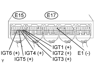 |
Measure the voltage of the E15 and E17 ECM connectors when the engine is cranked.
| Tester Connection | Specified Condition |
| E15-8 (IGT1) - E17-1 (E1) | 0.1 to 4.5 V |
| E15-9 (IGT2) - E17-1 (E1) | 0.1 to 4.5 V |
| E15-10 (IGT3) - E17-1 (E1) | 0.1 to 4.5 V |
| E15-11 (IGT4) - E17-1 (E1) | 0.1 to 4.5 V |
| E15-12 (IGT5) - E17-1 (E1) | 0.1 to 4.5 V |
| E15-13 (IGT6) - E17-1 (E1) | 0.1 to 4.5 V |
|
| ||||
| OK | |
| 6.INSPECT ECM (IGT1, IGT2, IGT3, IGT4, IGT5 OR IGT6 VOLTAGE) |
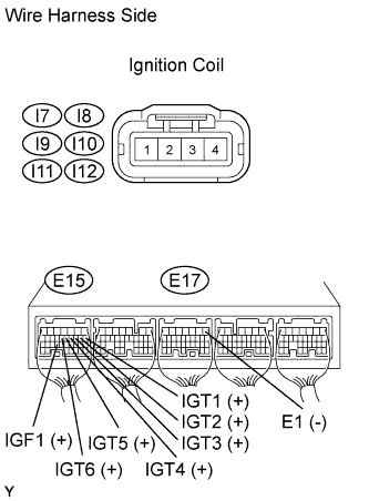 |
Disconnect the I7, I8, I9, I10, I11 or I12 ignition coil connector.
Measure the voltage of the E15 and E17 ECM connectors when the engine is cranked.
| Tester Connection | Specified Condition |
| E15-8 (IGT1) - E17-1 (E1) | 4.5 V or more |
| E15-9 (IGT2) - E17-1 (E1) | 4.5 V or more |
| E15-10 (IGT3) - E17-1 (E1) | 4.5 V or more |
| E15-11 (IGT4) - E17-1 (E1) | 4.5 V or more |
| E15-12 (IGT5) - E17-1 (E1) | 4.5 V or more |
| E15-13 (IGT6) - E17-1 (E1) | 4.5 V or more |
|
| ||||
| OK | |
| 7.INSPECT IGNITION COIL ASSEMBLY (POWER SOURCE) |
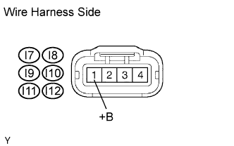 |
Disconnect the I7, I8, I9, I10, I11 or I12 ignition coil connector.
Turn the ignition switch ON.
Measure the voltage of the wire harness side connector.
| Tester Connection | Specified Condition |
| I7-1 (+B) - Body ground | 9 to 14 V |
| I8-1 (+B) - Body ground | 9 to 14 V |
| I9-1 (+B) - Body ground | 9 to 14 V |
| I10-1 (+B) - Body ground | 9 to 14 V |
| I11-1 (+B) - Body ground | 9 to 14 V |
| I12-1 (+B) - Body ground | 9 to 14 V |
|
| ||||
| NG | |
| 8.CHECK WIRE HARNESS (IGNITION COIL ASSEMBLY - IGNITION SWITCH) |
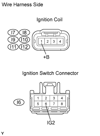 |
Disconnect the I7, I8, I9, I10, I11 or I12 ignition coil connector.
Disconnect the I6 ignition switch connector.
Measure the resistance of the wire harness side connectors.
| Tester Connection | Specified Condition |
| I7-1 (+B) - I6-6 (IG2) | Below 1 Ω |
| I8-1 (+B) - I6-6 (IG2) | Below 1 Ω |
| I9-1 (+B) - I6-6 (IG2) | Below 1 Ω |
| I10-1 (+B) - I6-6 (IG2) | Below 1 Ω |
| I11-1 (+B) - I6-6 (IG2) | Below 1 Ω |
| I12-1 (+B) - I6-6 (IG2) | Below 1 Ω |
| I7-1 (+B) or I6-6 (IG2) - Body ground | 10 kΩ or higher |
| I8-1 (+B) or I6-6 (IG2) - Body ground | 10 kΩ or higher |
| I9-1 (+B) or I6-6 (IG2) - Body ground | 10 kΩ or higher |
| I10-1 (+B) or I6-6 (IG2) - Body ground | 10 kΩ or higher |
| I11-1 (+B) or I6-6 (IG2) - Body ground | 10 kΩ or higher |
| I12-1 (+B) or I6-6 (IG2) - Body ground | 10 kΩ or higher |
|
| ||||
| OK | ||
| ||
