DTC P0300 Random / Multiple Cylinder Misfire Detected |
DTC P0301 Cylinder 1 Misfire Detected |
DTC P0302 Cylinder 2 Misfire Detected |
DTC P0303 Cylinder 3 Misfire Detected |
DTC P0304 Cylinder 4 Misfire Detected |
DTC P0305 Cylinder 5 Misfire Detected |
DTC P0306 Cylinder 6 Misfire Detected |
| DTC No. | DTC Detection Condition | Trouble Area |
| P0300 | Simultaneous misfiring of several cylinder detected (2 trip detection logic) |
|
| P0301 P0302 P0303 P0304 P0305 P0306 | Misfiring of specific cylinder detected (2 trip detection logic) |
|
| Item | Content |
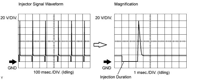
| Tester Connection | CH 1: #10 to #60 - E01 CH 2: INJF - E01 |
| Tool Setting | 20 V/DIV., 100 or 1 msec./DIV. |
| Condition | Idling |
| Engine Speed | Time |
| Idling | 3.5 minutes or more |
| 1,000 rpm | 3 minutes or more |
| 2,000 rpm | 1.5 minutes or more |
| 3,000 rpm | 1 minute or more |
| 1.CHECK ANY OTHER DTCS OUTPUT (IN ADDITION TO MISFIRE DTCS) |
Connect the intelligent tester to the DLC3.
Turn the ignition switch ON and turn the tester ON.
Turn the tester ON.
Enter the following menus: Powertrain / Engine and ECT / DTC.
Read DTCs.
| Display (DTC output) | Proceed to |
| P0300, P0301, P0302, P0303, P0304, P0305 or P0306 | A |
| P0300, P0301, P0302, P0303, P0304, P0305 or P0306 and other DTCs | B |
|
| ||||
| A | |
| 2.READ DATA LIST (MISFIRE RPM AND MISFIRE LOAD) |
Connect the intelligent tester to the DLC3.
Turn the ignition switch ON and turn the tester ON.
Enter the following menu items: Powertrain / Engine and ECT / Data List / Misfire RPM and Misfire Load.
Read and note the Misfire RPM (engine speed) and Misfire Load (engine load) values.
| NEXT | |
| 3.CHECK PCV HOSE CONNECTIONS |
|
| ||||
| OK | |
| 4.CHECK MISFIRE COUNT (CYL #10, #20, #30, #40, #50 AND #60) |
Connect the intelligent tester to the DLC3.
Turn the ignition switch ON and turn the tester ON.
Clear DTCs (Click here).
Enter the following menus: Powertrain / Engine and ECT / Data List / Cylinder #10 (to #60) Misfire Rate. *1
Allow the engine to idle.
Read each value of Cylinder #10 to #60 displayed on the tester. If no misfire counts occur in any cylinders, perform the following operations. *2
Move the shift lever to the drive position.
Repeat steps *1 and *2 above.
Check the Cylinder #10 to #60.
If misfire counts are still not displayed, perform steps *3 and *4 and then check the misfire counts again.
Drive the vehicle with the Misfire RPM and Misfire Load noted in step 2. *3
Read the Cylinder #10 to #60 or DTCs displayed on the tester. *4
| High Misfire Rate Cylinder | Proceed to |
| 1 or 2 cylinders have misfire counts | A |
| 3 cylinders or more have misfire counts | B |
|
| ||||
| A | |
| 5.CHECK SPARK PLUG |
 |
Remove the ignition coil and the spark plug of the misfiring cylinder.
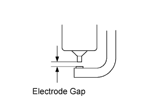
Measure the spark plug electrode gap.
Check the electrode for carbon deposits.
| Manufacturer | Product |
| DENSO | K20HR-U11 |
| NGK | LFR6C-11 |
|
| ||||
| OK | |
| 6.CHECK FOR SPARKS AND IGNITION |
Disconnect the injector connectors, in order to prevent the engine from starting.
Install the spark plug to the ignition coil.
Attach the spark plug assembly to the cylinder head cover.
Crank the engine for less than 2 seconds and check the spark.
|
| ||||
| OK | |
| 7.CHECK CYLINDER COMPRESSION PRESSURE OF MISFIRING CYLINDER |
Measure the cylinder compression pressure of the misfiring cylinder.
|
| ||||
| NG | ||
| ||
| 8.CHANGE NORMAL SPARK PLUG AND CHECK SPARK OF MISFIRING CYLINDER |
Change the installed spark plug to a spark plug that functions normally.
Perform a spark test.
Install the spark plug to the ignition coil and connect the ignition coil connector.
Disconnect the injector connector.
Ground the spark plug.
Check if sparks occur while the engine is being cranked.
|
| ||||
| OK | ||
| ||
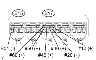
| 9.INSPECT ECM TERMINAL OF MISFIRING CYLINDER (#10, #20, #30, #40, #50 AND/OR #60 VOLTAGE) |
 |
Turn the ignition switch ON.
Measure the voltage between the applicable terminals of the E15 and E17 ECM connectors.
| Tester Connection | Specified Condition |
| #10 (E17-2) - (E15-7) E01 | 9 to 14 V |
| #20 (E17-3) - (E15-7) E01 | 9 to 14 V |
| #30 (E17-4) - (E15-7) E01 | 9 to 14 V |
| #40 (E17-5) - (E15-7) E01 | 9 to 14 V |
| #50 (E17-6) - (E15-7) E01 | 9 to 14 V |
| #60 (E17-7) - (E15-7) E01 | 9 to 14 V |
|
| ||||
| NG | |
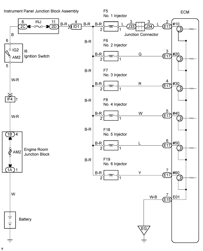
| 10.CHECK WIRE HARNESS (INJECTOR - ECM) |
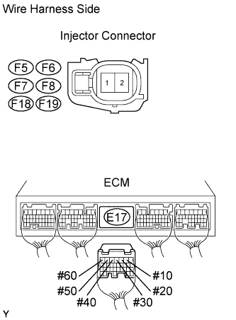 |
Disconnect the injector connector (of the misfiring cylinder).
Disconnect the E17 ECM connector.
Turn the ignition switch ON.
Measure the resistance and voltage of the wire harness side connectors.
| Cylinder | Tester Connection | Specified Condition |
| No. 1 | F5-1 - Ground | 11 to 14 V |
| No. 2 | F6-1 - Ground | 11 to 14 V |
| No. 3 | F7-1 - Ground | 11 to 14 V |
| No. 4 | F8-1 - Ground | 11 to 14 V |
| No. 5 | F18-1 - Ground | 11 to 14 V |
| No. 6 | F19-1 - Ground | 11 to 14 V |
| Cylinder | Tester Connection | Specified Condition |
| No. 1 | F5-1 or E17-2 (#10) - Ground | 10 kΩ or higher |
| No. 1 | F5-1 - E17-2 (#10) | Below 1 Ω |
| No. 2 | F6-1 or E17-3 (#20) - Ground | 10 kΩ or higher |
| No. 2 | F6-1 - E17-3 (#20) | Below 1 Ω |
| No. 3 | F7-1 or E17-4 (#30) - Ground | 10 kΩ or higher |
| No. 3 | F7-1 - E17-4 (#30) | Below 1 Ω |
| No. 4 | F8-1 or E17-5 (#40) - Ground | 10 kΩ or higher |
| No. 4 | F8-1 - E17-5 (#40) | Below 1 Ω |
| No. 5 | F18-1 or E17-6 (#50) - Ground | 10 kΩ or higher |
| No. 5 | F18-1 - E17-6 (#50) | Below 1 Ω |
| No. 6 | F19-1 or E17-7 (#60) - Ground | 10 kΩ or higher |
| No. 6 | F19-1 - E17-7 (#60) | Below 1 Ω |
|
| ||||
| OK | |
| 11.CHECK FUEL INJECTOR OF MISFIRING CYLINDER |
Check the injector injection (whether fuel volume is high or low, and whether injection pattern is poor).
|
| ||||
| OK | |
| 12.CHECK VALVE CLEARANCE OF MISFIRING CYLINDER |
|
| ||||
| OK | |
| 13.CHECK AIR INDUCTION SYSTEM |
Check the air induction system for vacuum leakage.
|
| ||||
| OK | |
| 14.CHECK VALVE TIMING (CHECK FOR LOOSE AND JUMPED TOOTH ON TIMING CHAIN) |
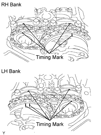 |
Remove the cylinder head cover.
Turn the crankshaft pulley, and align its groove with the timing mark "0" of the timing chain cover.
Check that the timing marks of the camshaft timing gears are aligned with the timing marks of the bearing cap as shown in the illustration.
If not, turn the crankshaft 1 revolution (360°) and align the marks as above.
|
| ||||
| OK | |
| 15.CHECK FUEL PRESSURE |
Check the fuel pressure.
|
| ||||
| OK | |
| 16.READ DATA LIST (COOLANT TEMP) |
Connect the intelligent tester to the DLC3.
Turn the ignition switch ON and turn the tester ON.
Enter the following menus items: Powertrain / Engine and ECT / Data List / Coolant Temp.
Read the Coolant Temp twice, when the engine is both cold and warmed up.
|
| ||||
| OK | |
| 17.READ DATA LIST (MAF) |
Connect the intelligent tester to the DLC3.
Turn the ignition switch ON and turn the tester ON.
Enter the following menu items: Powertrain / Engine and ECT / Data List / Coolant Temp and MAF.
Allow the engine to idle until the Coolant Temp reaches 75°C (167°F) or more.
Read the MAF with the engine in an idling condition and at an engine speed of 2,500 rpm.
|
| ||||
| OK | ||
| ||
