SFI SYSTEM > ECM Power Source Circuit |
| 1.INSPECT ECM (+B VOLTAGE) |
 |
Turn the ignition switch ON.
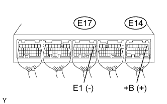
Measure the voltage of the ECM connectors.
| Tester Connection | Specified Condition |
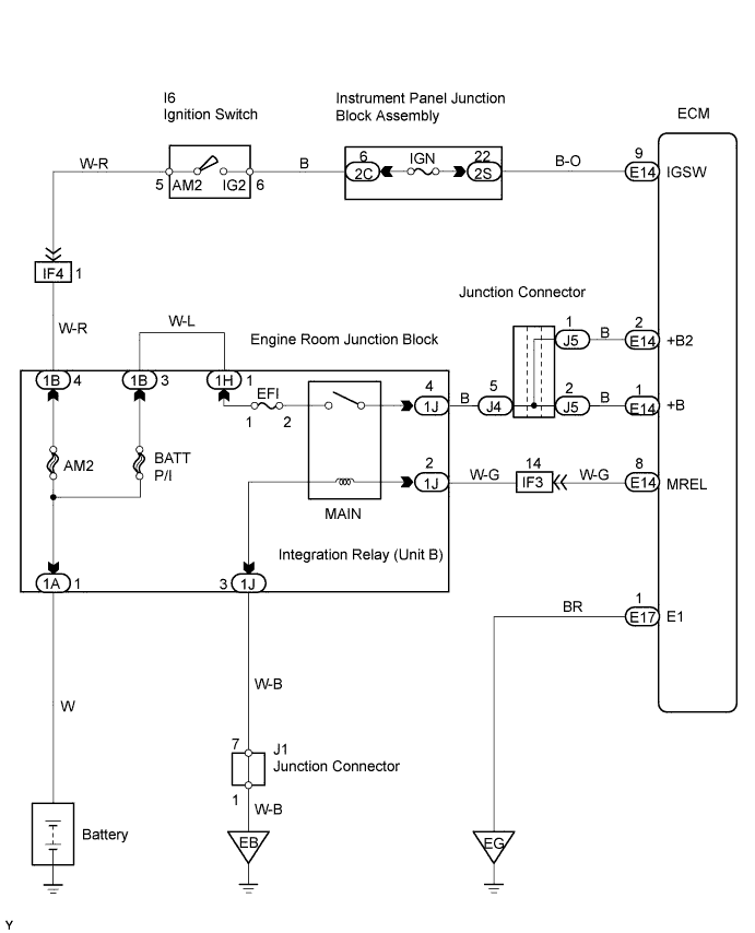
| E14-1 (+B) - E17-1 (E1) | 9 to 14 V |
|
| ||||
| NG | |
| 2.CHECK WIRE HARNESS (ECM - BODY GROUND) |
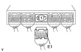 |
Disconnect the E17 ECM connector.
Measure the resistance of the wire harness side connector.
| Tester Connection | Specified Condition |
| E17-1 (E1) - Body ground | Below 1 Ω |
|
| ||||
| OK | |
| 3.INSPECT ECM (IGSW VOLTAGE) |
 |
Turn the ignition switch ON.
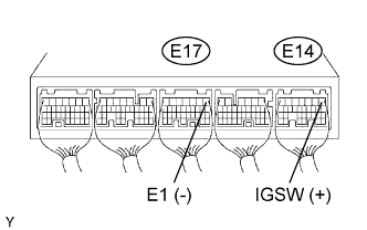
Measure the voltage of the ECM connectors.
| Tester Connection | Specified Condition |
| E14-9 (IGSW) - E17-1 (E1) | 9 to 14 V |
|
| ||||
| NG | |
| 4.INSPECT FUSE (IGN) |
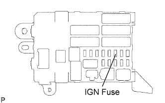 |
Remove the IGN fuse from the instrument panel junction block.
Measure the resistance of the fuse.
|
| ||||
| OK | |
| 5.INSPECT IGNITION OR STARTER SWITCH ASSEMBLY |
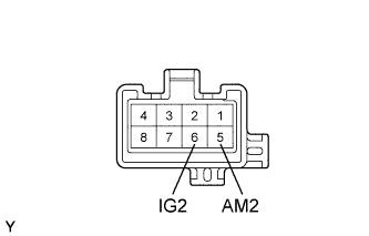 |
Disconnect the I6 ignition switch connector.
Measure the resistance of the switch.
| Tester Connection | Switch Condition | Specified Condition |
| 5 (AM2) - 6 (IG2) | OFF | 10 kΩ or higher |
| 5 (AM2) - 6 (IG2) | ON | Below 1 Ω |
|
| ||||
| OK | ||
| ||
| 6.INSPECT ECM (MREL VOLTAGE) |
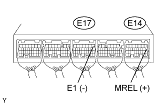 |
Turn the ignition switch ON.
Measure the voltage of the ECM connectors.
| Tester Connection | Specified Condition |
| E14-8 (MREL) - E17-1 (E1) | 9 to 14 V |
|
| ||||
| OK | |
| 7.INSPECT FUSE (EFI) |
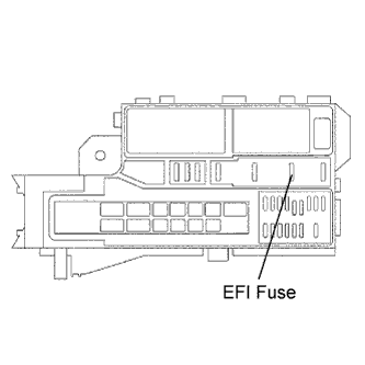 |
Remove the EFI fuse from the engine room junction block.
Measure the resistance of the fuse.
|
| ||||
| OK | |
| 8.INSPECT INTEGRATION RELAY (MAIN RELAY) |
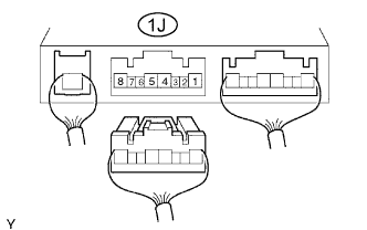 |
Disconnect the integration relay from the engine room junction block.
Measure the voltage of the integration relay.
| Tester Connection | Condition | Specified Condition |
| 1J-4 - Body ground | Ignition switch ON | 10 to 14 V |
|
| ||||
| OK | |
| 9.CHECK WIRE HARNESS (INTEGRATION RELAY- ECM, INTEGRATION RELAY - BODY GROUND) |
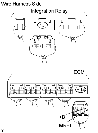 |
Disconnect the 1J integration relay connector from the engine room junction block.
Disconnect the E14 ECM connector.
Measure the resistance of the wire harness side connectors.
| Tester Connection | Specified Condition |
| 1J-2 - E14-8 (MREL) | Below 1 Ω |
| 1J-4 - E14-1 (+B) | Below 1 Ω |
| 1J-3 - Body ground | Below 1 Ω |
| 1J-2 or E14-8 (MREL) - Body ground | 10 kΩ or higher |
| 1J-4 or E14-1 (+B) - Body ground | 10 kΩ or higher |
|
| ||||
| OK | ||
| ||
