SFI SYSTEM > Fuel Pump Control Circuit |
| 1.CHECK FUEL PUMP OPERATION |
Check if there is pressure in the fuel inlet hose.
|
| ||||
| NG | |
| 2.PERFORM ACTIVE TEST (OPERATE OF CIRCUIT OPENING RELAY) |
Connect the intelligent tester to the DLC3.
Turn the ignition switch ON and turn the tester ON.
Enter the following menus: Powertrain / Engine and ECT / Active Test / Fuel Pump / Speed.
Check whether operating sounds can be heard while operating the relay using the relay.
|
| ||||
| NG | |
| 3.INSPECT INTEGRATION RELAY (C/OPN RELAY) |
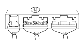 |
Remove the integration relay from the engine room junction block.
Measure the voltage of the C/OPN relay.
| Terminal Connection | Condition | Specified Condition |
| 1J-8 - Body ground | Ignition switch ON | 10 to 14 V |
|
| ||||
| OK | |
| 4.INSPECT ECM (FC VOLTAGE) |
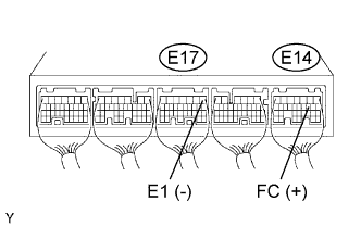 |
Turn the ignition switch ON.
Measure the voltage of the ECM connectors.
| Tester Connection | Specified Condition |
| E14-10 (FC) - E17-1 (E1) | 9 to 14 V |
|
| ||||
| NG | ||
| ||
| 5.INSPECT ECM POWER SOURCE CIRCUIT |
|
| ||||
| OK | |
| 6.INSPECT RELAY (Marking: F/PMP) |
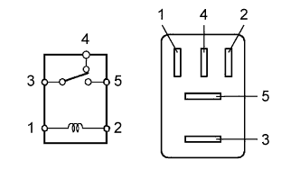 |
Remove the F/PMP relay from the engine room relay block.
Measure the resistance of the relay.
| Tester Connection | Specified Condition |
| 3 - 4 | Below 1 Ω |
| 3 - 5 | 10 kΩ or higher |
| 3 - 4 | 10 kΩ or higher (when battery voltage applied to terminals 1 and 2) |
| 3 - 5 | Below 1 Ω (when battery voltage applied to terminals 1 and 2) |
|
| ||||
| OK | |
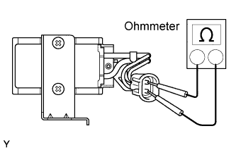
| 7.INSPECT FUEL PUMP |
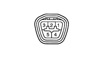 |
Inspect fuel pump resistance.
Measure the resistance between terminals 4 and 5.
Inspect fuel pump operation.
Apply battery voltage to both terminals. Check that the pump operates.
|
| ||||
| OK | |
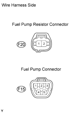
| 8.CHECK WIRE HARNESS (FUEL PUMP - F/PMP RELAY, FUEL PUMP - BODY GROUND) |
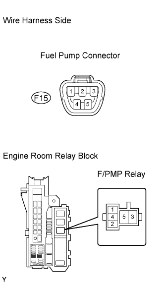  |
Check the wire harness between the fuel pump and fuel pump relay.
Disconnect the F15 fuel pump connector.
Remove the F/PMP relay from the engine room relay block.
Measure the resistance of the wire harness side connectors.
| Tester Connection | Specified Condition |
| F15-5 - Body ground | Below 1 Ω |
| F15-4 or F/PMP relay (4) - Body ground | 10 kΩ or higher |
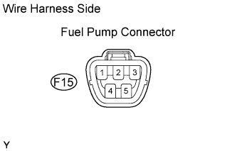
Check the wire harness between the fuel pump and body ground.
Disconnect the F15 fuel pump connector.
Measure the resistance of the wire harness side connector.
| Tester Connection | Specified Condition |
| F15-5 - Body ground | Below 1 Ω |
|
| ||||
| OK | |
| 9.CHECK WIRE HARNESS (INTEGRATION RELAY - F/PMP RELAY) |
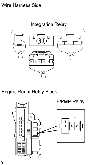 |
Disconnect the 1J integration relay connector from the engine room junction block.
Remove the F/PMP relay from the engine room relay block.
Measure the resistance of the wire harness side connectors.
| Tester Connection | Specified Condition |
| 1J-8 - Fuel pump relay (3) | Below 1 Ω |
| 1J-8 or Fuel pump relay (3) - Body ground | 10 kΩ or higher |
|
| ||||
| OK | ||
| ||
| 10.INSPECT RELAY (Marking: F/PMP) |
|
Remove the F/PMP relay from the engine room relay block.
Measure the resistance of the relay.
| Tester Connection | Specified Condition |
| 3 - 4 | Below 1 Ω |
| 3 - 5 | 10 kΩ or higher |
| 3 - 4 | 10 kΩ or higher (when battery voltage applied to terminals 1 and 2) |
| 3 - 5 | Below 1 Ω (when battery voltage applied to terminals 1 and 2) |
|
| ||||
| OK | |
| 11.INSPECT FUEL PUMP RESISTOR (RESISTANCE) |
 |
Inspect the fuel pump resistor resistance.
Measure the resistance.
|
| ||||
| OK | |
| 12.CHECK WIRE HARNESS (F/PMP RELAY - FUEL PUMP RESISTOR, FUEL PUMP RESISTOR - FUEL PUMP) |
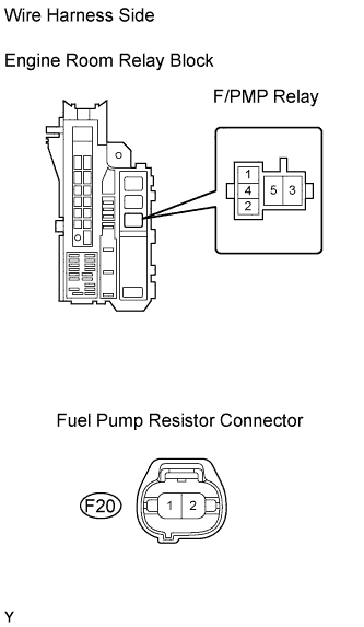  |
Check the wire harness between the F/PMP relay and fuel pump resistor.
Remove the fuel pump relay from the engine room relay block.
Disconnect the F20 fuel pump resistor connector.
Measure the resistance of the wire harness side connectors.
| Tester Connection | Specified Condition |
| F/PMP relay (5) - F20-1 (+B) | Below 1 Ω |
| F/PMP relay (5) or F20-1 (+B) - Body ground | 10 kΩ or higher |
Check the wire harness between the fuel pump relay and fuel pump.
Disconnect the F20 fuel pump resistor connector.
Disconnect the F15 fuel pump connector.
Measure the resistance of the wire harness side connectors.
| Tester Connection | Specified Condition |
| F20-2 (FP) - F15-4 | Below 1 Ω |
| F20-2 (FP) or F15-4 - Body ground | 10 kΩ or higher |
|
| ||||
| NG | ||
| ||
