DTC P2195 Oxygen (A/F) Sensor Signal Stuck Lean (Bank 1 Sensor 1) |
DTC P2196 Oxygen (A/F) Sensor Signal Stuck Rich (Bank 1 Sensor 1) |
DTC P2197 Oxygen (A/F) Sensor Signal Stuck Lean (Bank 2 Sensor 1) |
DTC P2198 Oxygen (A/F) Sensor Signal Stuck Rich (Bank 2 Sensor 1) |
| DTC No. | DTC Detection Condition | Trouble Area |
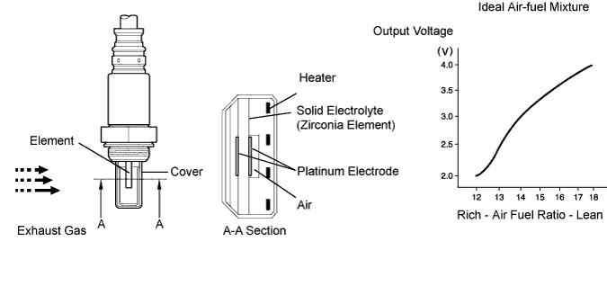
| P2195 P2197 | Conditions (a) continue for 10 seconds or more (a) A/F sensor voltage more than 3.8 V |
|
| P2195 P2197 | While fuel-cut operation performed (during vehicle deceleration), A/F sensor current 3.6 mA or more for 3 seconds |
|
| P2196 P2198 | Conditions (a) continue for 10 seconds or more (a) A/F sensor voltage less than 2.8 V |
|
| P2196 P2198 | While fuel-cut operation performed (during vehicle deceleration), A/F sensor current 1.4 mA for 3 seconds (2 trip detection logic) |
|
| Tester Display (Sensor) | Injection Volume | Status | Voltage |
| AFS B1S1 or AFS B2S1 (A/F) | +25% | Rich | Less than 3.0 |
| AFS B1S1 or AFS B2S1 (A/F) | -12.5% | Lean | More than 3.35 |
| O2S B1S2 or O2S B2S2 (heated oxygen sensor) | +25% | Rich | More than 0.55 |
| O2S B1S2 or O2S B2S2 (heated oxygen sensor) | -12.5% | Lean | Less than 0.4 |
| Case | A/F Sensor (Sensor 1) Output Voltage | Heated Oxygen Sensor (Sensor 2) Output Voltage | Main Suspected Trouble Areas | ||
| 1 | Injection volume +25% -12.5% |  | Injection volume +25% -12.5% | | - |
| Output voltage More than 3.35 V Less than 3.0 V |  | Output voltage More than 0.55 V Less than 0.4 V |  | ||
| 2 | Injection volume +25% -12.5% | | Injection volume +25% -12.5% | |
|
| Output voltage Almost no reaction |  | Output voltage More than 0.55 V Less than 0.4 V | | ||
| 3 | Injection volume +25% -12.5% | | Injection volume +25% -12.5% | |
|
| Output voltage More than 3.35 V Less than 3.0 V | | Output voltage Almost no reaction | | ||
| 4 | Injection volume +25% -12.5% | | Injection volume +25% -12.5% | |
|
| Output voltage Almost no reaction | | Output voltage Almost no reaction | | ||
| 1.CHECK ANY OTHER DTCS OUTPUT (IN ADDITION TO P2195, P2196, P2197 OR P2198) |
Connect the intelligent tester to the DLC3.
Turn the ignition switch ON and turn the tester ON.
Enter the following menus: Powertrain / Engine and ECT / DTC.
Read the DTCs.
| Display (DTC output) | Proceed to |
| P2195, P2196, P2197 or P2198 | A |
| DTCs other than P2195, P2196, P2197 or P2198 | B |
|
| ||||
| A | |
| 2.READ DATA LIST (OUTPUT VOLTAGE OF A/F SENSOR) |
Connect the intelligent tester to the DLC3.
Warm up the A/F sensors (bank 1, 2 sensor 1) with the engine at 2,500 rpm for approximately 90 seconds.
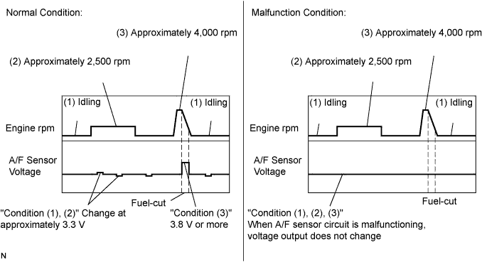
Read A/F sensor voltage output on the intelligent tester.
Enter the following menus: Powertrain / Engine and ECT / Data List.
Select AFS B1S1 or AFS B2S1 / Engine Speed.
Monitor the A/F sensor voltage carefully.
Check the A/F sensor voltage under the condition as follows.
(1) Allow engine to idle for 30 seconds.
(2) Engine is racing at approximately 2,500 rpm (when engine revolution is not suddenly changed).
(3) Raise the engine speed to 4,000 rpm and release the accelerator pedal fully closed quickly.
|
| ||||
| NG | |
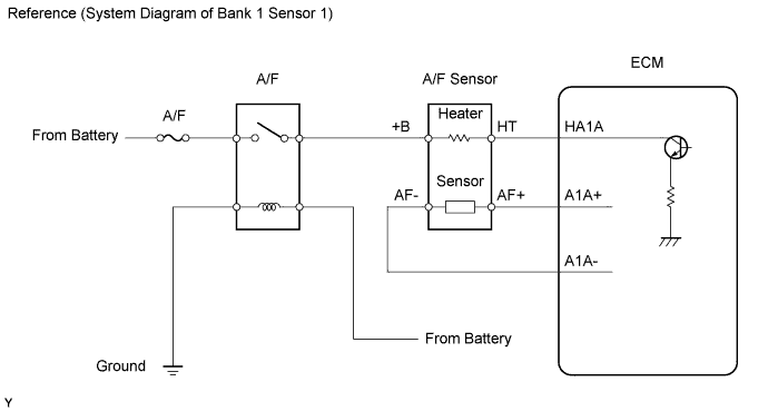
| 3.INSPECT AIR FUEL RATIO SENSOR (HEATER RESISTANCE) |
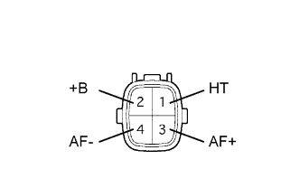 |
Disconnect the A/F sensor connector.
Measure the resistance of the A/F sensor.
| Tester Connection | Condition | Specified Condition |
| 1 (HT) - 2 (+B) | 20°C (68°F) | 1.8 to 3.4 Ω |
| 1 (HT) - 4 (AF-) | - | 10 kΩ or higher |
|
| ||||
| OK | |
| 4.INSPECT RELAY (Making: A/F) |
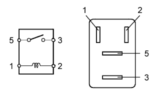 |
Remove the A/F heater relay from the engine room relay block.
Measure the resistance of the relay.
| Terminal No. | Specified Condition |
| 3 - 5 | 10 kΩ or higher |
| 3 - 5 | Below 1 Ω (when battery voltage is applied to terminals 1 and 2) |
|
| ||||
| OK | |
| 5.CHECK HARNESS AND CONNECTOR (A/F SENSOR - ECM) |
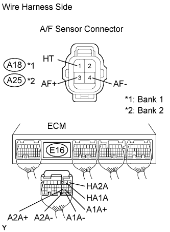  |
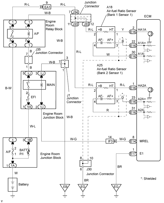
Disconnect the A18 or A25 A/F sensor connector.
Disconnect the E16 ECM connector.
Measure the resistance of the wire harness side connectors.
| Tester Connection | Specified Condition |
| A18-1 (HT) - E16-2 (HA1A) | Below 1 Ω |
| A18-3 (AF+) - E16-22 (A1A+) | Below 1 Ω |
| A18-4 (AF-) - E16-30 (A1A-) | Below 1 Ω |
| A25-1 (HT) - E16-1 (HA2A) | Below 1 Ω |
| A25-3 (AF+) - E16-23 (A2A+) | Below 1 Ω |
| A25-4 (AF-) - E16-31 (A2A-) | Below 1 Ω |
| A18-1 (HT) or E16-2 (HA1A) - Body ground | 10 kΩ or higher |
| A18-3 (AF+) or E16-22 (A1A+) - Body ground | 10 kΩ or higher |
| A18-4 (AF-) or E16-30 (A1A-) - Body ground | 10 kΩ or higher |
| A25-1 (HT) or E16-1 (HA2A) - Body ground | 10 kΩ or higher |
| A25-3 (AF+) or E16-23 (A2A+) - Body ground | 10 kΩ or higher |
| A25-4 (AF-) or E16-31 (A2A-) - Body ground | 10 kΩ or higher |
|
| ||||
| OK | |
| 6.CHECK AIR INDUCTION SYSTEM |
Check for vacuum leaks in air induction system.
|
| ||||
| OK | |
| 7.CHECK FUEL PRESSURE |
Check fuel pressure (high or low fuel pressure).
|
| ||||
| OK | |
| 8.INSPECT FUEL INJECTOR ASSEMBLY |
Check injector injection (high or low fuel pressure).
|
| ||||
| OK | |
| 9.REPLACE AIR FUEL RATIO SENSOR |
| NEXT | |
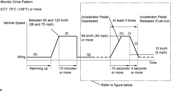
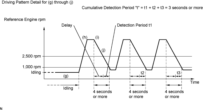
| 10.PERFORM CONFIRMATION DRIVING PATTERN |
| NEXT | |
| 11.CHECK WHETHER DTC OUTPUT RECURS (DTC P2195, P2196, P2197 OR P2198) |
Connect the intelligent tester to the DLC3.
Turn the ignition switch ON and turn the tester ON .
Enter the following menus: Powertrain / Engine and ECT / DTC.
Read the DTCs.
| Display | Proceed to |
| No output | A |
| P2195, P2196, P2197 or P2198 (A/F sensor pending DTCs) | B |
|
| ||||
| A | |
| 12.CONFIRM IF VEHICLE HAS RUN OUT OF FUEL IN PAST |
|
| ||||
| YES | ||
| ||
| 13.PERFORM CONFIRMATION DRIVING PATTERN |
| NEXT | |
| 14.CHECK WHETHER DTC OUTPUT RECURS (DTC P2195, P2196, P2197 OR P2198) |
Connect the intelligent tester to the DLC3.
Turn the ignition switch ON and turn the tester ON .
Enter the following menus: Powertrain / Engine and ECT / DTC.
Read the DTCs.
| Display | Proceed to |
| No output | A |
| P2195, P2196, P2197 or P2198 (A/F sensor pending DTCs) | B |
|
| ||||
| A | |
| 15.REPLACE AIR FUEL RATIO SENSOR |
| NEXT | |
| 16.PERFORM CONFIRMATION DRIVING PATTERN |
| NEXT | |
| 17.CHECK WHETHER DTC OUTPUT RECURS (DTC P2195, P2196, P2197 OR P2198) |
Connect the intelligent tester to the DLC3.
Turn the ignition switch ON and turn the tester ON.
Enter the following menus: Powertrain / Engine and ECT / DTC.
Read the DTCs.
| Display | Proceed to |
| No output | A |
| P2195, P2196, P2197 or P2198 (A/F sensor pending DTCs) | B |
|
| ||||
| A | |
| 18.CONFIRM IF VEHICLE HAS RUN OUT OF FUEL IN PAST |
|
| ||||
| YES | ||
| ||
