DTC P0031 Oxygen (A/F) Sensor Heater Control Circuit Low (Bank 1 Sensor 1) |
DTC P0032 Oxygen (A/F) Sensor Heater Control Circuit High (Bank 1 Sensor 1) |
| DTC No. | DTC Detection Condition | Trouble Area |
| P0031 | Heated current is 0.8 A or less when heater operates (1 trip detection logic) |
|
| P0032 | Heated current exceeds 10 A when heater operates (1 trip detection logic) |
|
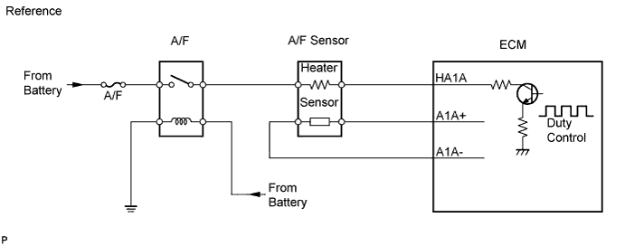
| 1.INSPECT AIR FUEL RATIO SENSOR (HEATER RESISTANCE) |
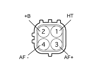 |
Disconnect the A18 sensor connector.
Measure the resistance of the sensor.
| Tester Connection | Condition | Specified Condition |
| 1 (HT) - 2 (+B) | 20°C (68°F) | 1.8 to 3.4 Ω |
| 1 (HT) - 4 (AF-) | Always | 10 kΩ or higher |
|
| ||||
| OK | |
| 2.INSPECT RELAY (MARKING: A/F) |
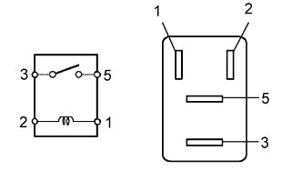 |
Remove the A/F relay from the engine room relay block.
Measure the resistance of the relay.
| Tester Connection | Specified Condition |
| 3 - 5 | 10 kΩ or higher |
| 3 - 5 | Below 1 Ω (when battery voltage applied to terminals 1 and 2) |
|
| ||||
| OK | |
| 3.CHECK ECM (HA1A VOLTAGE) |
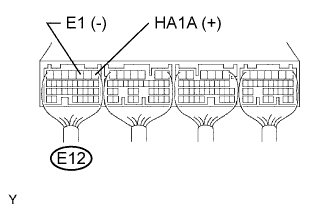 |
Turn the ignition switch ON.
Measure the voltage of the E12 ECM connector.
| Tester Connection | Specified Condition |
| E12-1 (HA1A) - E12-3 (E1) | 9 to 14 V |
|
| ||||
| NG | |
| 4.CHECK WIRE HARNESS (A/F SENSOR - ECM AND A/F RELAY) |
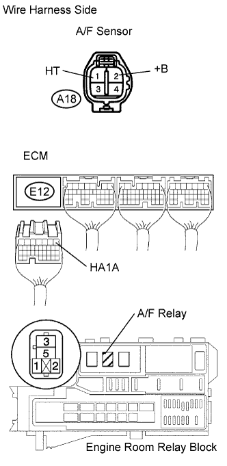 |
Disconnect the A18 A/F sensor connector.
Disconnect the E12 ECM connector.
Remove the A/F relay from the engine room relay block.
Measure the resistance of the wire harness side connectors.
| Tester Connection | Specified Condition |
| A18-1 (HT) - E12-1 (HA1A) | Below 1 Ω |
| A18-2 (+B) - R/B A/F relay terminal 5 | Below 1 Ω |
| A18-1 (HT) or E12-1 (HA1A) - Body ground | 10 kΩ or higher |
| A18-2 (+B) or R/B A/F relay terminal 5 - Body ground | 10 kΩ or higher |
|
| ||||
| OK | ||
| ||
