DTC P0340 Camshaft Position Sensor Circuit Malfunction |
DTC P0342 Camshaft Position Sensor "A" Circuit Low Input (Bank 1 or Single Sensor) |
DTC P0343 Camshaft Position Sensor "A" Circuit High Input (Bank 1 or Single Sensor) |
DTC P0345 Camshaft Position Sensor "A" Circuit (Bank 2) |
DTC P0347 Camshaft Position Sensor "A" Circuit Low Input (Bank 2) |
DTC P0348 Camshaft Position Sensor "A" Circuit High Input (Bank 2) |
| DTC No. | DTC Detection Condition | Trouble Area |
| P0340 P0345 | STA ON: No camshaft position sensor signal to ECM during cranking for 4 seconds or more STA OFF: No camshaft position sensor signal to ECM with engine speed 600 or more |
|
| P0342 P0347 | Output voltage of Variable Valve Timing (VVT) sensor 0.3 V or less for 5 seconds (1 trip detection logic) |
|
| P0343 P0348 | Output voltage of VVT sensor 4.7 V or more for 5 seconds (1 trip detection logic) |
|
| 1.CHECK ECM TERMINAL VOLTAGE |
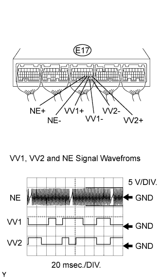 |
Inspect using an oscilloscope.
While the engine is idling, check the waveform of the ECM connector.
| Tester Connection | E17-19 (VV1+) - E17-29 (VV1-) E17-18 (VV2+) - E17-28 (VV2-) E17-21 (NE+) - E17-20 (NE-) |
| Tool Setting | 5 V/DIV., 20 msec./DIV. |
| Condition | Idling |
|
| ||||
| OK | |
| 2.CHECK WIRE HARNESS (SENSOR POWER SOURCE) |
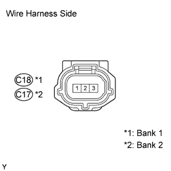 |
Disconnect the C17 or C18 VVT sensor connector.
Turn the ignition switch ON.
Measure the voltage of the wire harness side connector.
| Tester Connection | Specified Condition |
| C18-3 (VC) - Body ground | 4.5 to 5.5 V |
| C17-3 (VC) - Body ground | 4.5 to 5.5 V |
|
| ||||
| OK | |
| 3.CHECK WIRE HARNESS (VVT SENSOR - ECM) |
 |
Disconnect the C17 and C18 VVT sensor connectors.
Disconnect the E17 ECM connector.
Measure the resistance of the wire harness side connectors.
| Tester Connection | Specified Condition |
| C18-1 (VVR+) - E17-19 (VV1+) | Below 1 Ω |
| C17-1 (VVL+) - E17-18 (VV2+) | Below 1 Ω |
| C18-2 (VVR-) - E17-29 (VV1-) | Below 1 Ω |
| C17-2 (VVL-) - E17-28 (VV2-) | Below 1 Ω |
| C18-1 (VVR+) or E17-19 (VV1+) - Body ground | 10 kΩ or higher |
| C17-1 (VVL+) or E17-18 (VV2+) - Body ground | 10 kΩ or higher |
| C18-2 (VVR-) or E17-29 (VV1-) - Body ground | 10 kΩ or higher |
| C17-2 (VVL-) or E17-28 (VV2-) - Body ground | 10 kΩ or higher |
|
| ||||
| OK | |
| 4.CHECK SENSOR INSTALLATION (VVT SENSOR) |
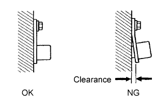 |
Check the VVT sensor installation.
|
| ||||
| OK | |
| 5.CHECK CAMSHAFT TIMING GEAR ASSEMBLY (TEETH OF PLATE) |
Check the teeth of the signal plate.
|
| ||||
| OK | ||
| ||
