DTC    P0724    Brake Switch "B" Circuit High

for Preparation Click here


DESCRIPTION

The purpose of this circuit is to prevent the engine from stalling while driving in the lock-up condition when the brakes are suddenly applied.
When the brake pedal is depressed, this switch sends a signal to the ECM. Then the ECM cancels the operation of the lock-up clutch while braking is in progress.

DTC No.
DTC Detection Condition
Trouble Area
P0724
Stop light switch remains ON even when vehicle is driven in STOP (less than 3 km/h (2 mph)) and GO (30 km/h (19 mph) or more) pattern 5 times (2 trip detection logic)
  1. Short in stop light switch signal circuit
  2. Stop light switch
  3. ECM

MONITOR DESCRIPTION

This DTC indicates that the stop light switch remains ON. When the stop light switch remains ON during STOP and GO driving, the ECM interprets this as a fault in the stop light switch. Then the MIL illuminates and the ECM stores the DTC. The vehicle must STOP (less than 3 km/h (2 mph)) and GO (30 km/h (19 mph) or more) 5 times for 2 driving cycles in order for the DTC to be output.

WIRING DIAGRAM


G034504E01


INSPECTION PROCEDURE

1.READ VALUE OF DATA LIST (STP SIGNAL)

HINT:
Using the intelligent tester's Data List allows switch, sensor, actuator and other item values to be read without removing any parts. Reading the Data List early in troubleshooting is one way to save time.

  1. Warm up the engine.

  1. Turn the ignition switch OFF.

  1. Connect the intelligent tester to the DLC3.

  1. Turn the ignition switch ON and push the tester main switch ON.

  1. Enter the following menus: Powertrain / Engine and ECT / Data List.

  1. Follow the instructions on the tester and read the Data List.


Item
Measurement Item/
Range (Display)
Normal Condition
Diagnostic Note
Stop Light Switch
Stop light switch status/
ON or OFF
  1. Brake pedal is depressed: ON
  2. Brake pedal is released: OFF
-

CAUTION:
In the table above, the values listed under "Normal Condition" are reference values. Do not depend solely on these reference values when deciding whether a part is faulty or not.


OK
Go to step 3
NG


2.INSPECT STOP LIGHT SWITCH


    E065594E02
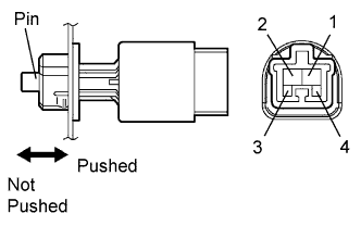
  1. Remove the stop light switch.

  1. Measure the resistance of the switch.

    Standard resistance:
    Tester Connection
    Switch Condition
    Specified Condition
    1 - 2
    Pin pushed
    (pedal released)
    10 kΩ or higher
    1 - 2
    Pin not pushed
    (pedal depressed)
    Below 1 Ω
    3 - 4
    Pin pushed
    (pedal released)
    10 kΩ or higher
    3 - 4
    Pin not pushed
    (pedal depressed)
    Below 1 Ω


NG
REPLACE STOP LIGHT SWITCH
OK


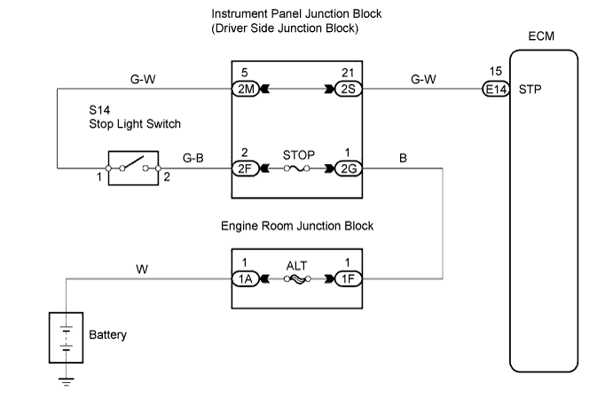
3.CHECK WIRE HARNESS (ECM - BATTERY)


    G035614E08
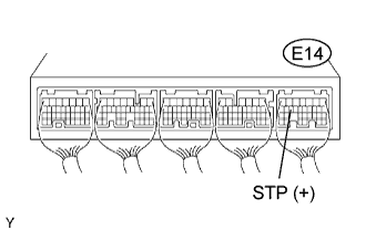
  1. Measure the voltage of the wire harness side connector.

    Standard voltage:
    Tester Connection
    Condition
    Specified Condition
    E14-15 (STP) - Body ground
    Brake pedal is depressed
    10 to 14 V
    E14-15 (STP) - Body ground
    Brake pedal is released
    Below 1 V


NG
REPAIR OR REPLACE HARNESS AND CONNECTOR
OK

REPLACE ECM