Symbols (Terminals No.)
| Wiring Color
| Terminal Description
| Condition
| Specified Condition
|
L4 (E17-13) - E1 (E17-1)
| G-W - BR
| L4 shift position switch signal
| Ignition switch ON and transfer shift lever on L4
| Below 1 V
|
L4 (E17-13) - E1 (E17-1)
| G-W - BR
| L4 shift position switch signal
| Ignition switch ON and transfer shift lever not on L4
| 10 to 14 V
|
TFN (E16-25) - E1 (E17-1)
| W-G - BR
| N shift position switch signal
| Ignition switch ON and transfer shift lever on N
| Below 1 V
|
TFN (E16-25) - E1 (E17-1)
| W-G - BR
| N shift position switch signal
| Ignition switch ON and transfer shift lever not on N
| 10 to 14 V
|
L (E13-9) - E1 (E17-1)
| GR-L - BR
| L shift position switch signal
| Ignition switch ON and transfer shift lever on L
| 10 to 14 V
|
L (E13-9) - E1 (E17-1)
| GR-L - BR
| L shift position switch signal
| Ignition switch ON and transfer shift lever not on L
| Below 1 V
|
2 (E13-10) - E1 (E17-1)
| G-R - BR
| 2 shift position switch signal
| Ignition switch ON and transfer shift lever on 2 and L
| 10 to 14 V
|
2 (E13-10) - E1 (E17-1)
| G-R - BR
| 2 shift position switch signal
| Ignition switch ON and transfer shift lever not on 2 and L
| Below 1 V
|
R (E13 -11) - E1 (E17-1)
| R-Y - BR
| R shift position switch signal
| Ignition switch ON and transfer shift lever on R
| 10 to 14 V
|
R (E13 -11) - E1 (E17-1)
| R-Y - BR
| R shift position switch signal
| Ignition switch ON and transfer shift lever not on R
| Below 1 V
|
D (E13-21) - E1 (E17-1)
| G-Y - BR
| D shift position switch signal
| Ignition switch ON and transfer shift lever on D or 4
| 10 to 14 V
|
D (E13-21) - E1 (E17-1)
| G-Y - BR
| D shift position switch signal
| Ignition switch ON and transfer shift lever not on D or 4
| Below 1 V
|
3 (E13-19) - E1 (E17-1)
| L - BR
| 3 shift position switch signal
| Ignition switch ON and transfer shift lever on 3
| 10 to 14 V
|
3 (E13-19) - E1 (E17-1)
| L - BR
| 3 shift position switch signal
| Ignition switch ON and transfer shift lever not on 3
| Below 1 V
|
4 (E13-20) - E1 (E17-1)
| G-O - BR
| 4 shift position switch signal
| Ignition switch ON and transfer shift lever on 4
| 10 to 14 V
|
4 (E13-20) - E1 (E17-1)
| G-O - BR
| 4 shift position switch signal
| Ignition switch ON and transfer shift lever not on 4
| Below 1 V
|
STP (E14-15) - E1 (E17-1)
| G-W - BR
| Stop light switch signal
| Brake pedal is depressed
| 7.5 to 14 V
|
STP (E14-15) - E1 (E17-1)
| G-W - BR
| Stop light switch signal
| Brake pedal is released
| Below 1.5 V
|
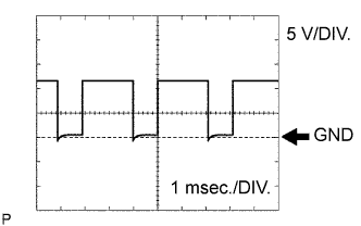
SLU+ (E16-15) - SLU- (E16-14)
| L - W
| SLU solenoid signal
| 5th (lock-up) gear
| Pulse generation
(see waveform 1)
|
S2 (E16-10) - E1 (E17-1)
| W-L - BR
| S2 solenoid signal
| 2nd or 3rd gear
| 10 to 14 V
|
S2 (E16-10) - E1 (E17-1)
| W-L - BR
| S2 solenoid signal
| 1st, 4th or 5th gear
| Below 1 V
|
S1 (E16-11) - E1 (E17-1)
| GR - BR
| S1 solenoid signal
| 1st or 2nd gear
| 10 to 14 V
|
S1 (E16-11) - E1 (E17-1)
| GR - BR
| S1 solenoid signal
| 3rd, 4th or 5th gear
| Below 1 V
|
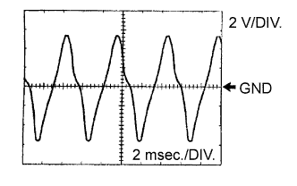
SLT+ (E16-13) - SLT- (E16-12)
| G-Y - L-B
| SLT solenoid signal
| Engine idle speed
| Pulse generation
(see waveform 2)
|
SR (E16-9) - E1 (E17-1)
| G - BR
| SR solenoid signal
| 5th gear
| 10 to 14 V
|
SR (E16-9) - E1 (E17-1)
| G - BR
| SR solenoid signal
| 1st gear
| Below 1 V
|
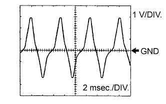
SL2+ (E16-17) - SL2- (E16-16)
| G-B - G-R
| SL2 solenoid signal
| Engine idle speed
| Pulse generation
(see waveform 3)
|
SL1+ (E16-19) - SL1- (E16 - 18)
| G-W - P-L
| SL1 solenoid signal
| Engine idle speed
| Pulse generation
(see waveform 4)
|
THO1 (E16-24) - E2 (E15-28)
| W-R - BR
| No. 1 ATF temperature sensor signal
| No. 1 ATF temperature: 115°C (239°F) or more
| Below 1.5 V
|
THO2 (E16-32) - E2 (E15-28)
| B-Y - BR
| No. 2 ATF temperature sensor signal
| No. 2 ATF temperature: 115°C (239°F) or more
| Below 1.5 V
|
SP2+ (E16-34) - SP2- (E16-26)
| V - P
| Speed sensor (SP2) signal
| Vehicle speed 20 km/h (12 mph)
| Pulse generation
(see waveform 5)
|
NT+ (E16-35) - NT- (E16-27)
| L - Y
| Speed sensor (NT) signal
| Engine idle speed
| Pulse generation
(see waveform 6)
|
NSW (E16-8) - E1 (E17-1)
| L-Y - BR
| PNP switch signal
| Ignition switch ON and shift lever on P or N
| Below 2 V
|
NSW (E16-8) - E1 (E17-1)
| L-Y - BR
| PNP switch signal
| Ignition switch ON and shift lever not on P or N
| 10 to 14 V
|