ECD SYSTEM > Lack of Power or Hesitation |
| Malfunction Condition | Main Trouble Areas | Related Trouble Areas |
| (a) Injector malfunctions
|
|
| 1.CHECK WIRE HARNESS IN ENGINE ROOM |
Check the wire harness and connector connections.
|
| ||||
| OK | |
| 2.PERFORM CONFIRMATION DRIVING PATTERN |
Enter CHECK MODE (Click here).
Fully warm up the engine.
Allow the engine to idle for 5 minutes or more.
Drive the vehicle at more than 40 km/h (25 mph) for several tens of seconds.
Decelerate and stop the vehicle.
Repeat steps (d) and (e) 4 times or more.
Stop the engine and wait for at least 10 seconds.
Repeat steps (d) and (g) described above (to set DTCs relating to the throttle valve).
Drive the vehicle at more than 70 km/h (43 mph) for at least 1 minute (to set DTCs relating to the supply pump).
| NEXT | |
| 3.READ OUTPUT DTC (RELATING TO ENGINE) |
Enter the following menus: Powertrain / Engine / DTC.
Read pending DTCs.
| Display (DTC Output) | Proceed to |
| No DTCs | A |
| Engine related DTCs (Click here) | B |
|
| ||||
| A | |
| 4.PERFORM ACTIVE TEST BY INTELLIGENT TESTER (TEST THE FUEL LEAK) |
Connect the intelligent tester to the DLC3.
Start the engine and turn the intelligent tester ON.
Enter the following menus: Powertrain / Engine / Active Test / Test the Fuel Leak.
Visually check the supply pump, injector and fuel line located between the supply pump and common rail for fuel leaks and fuel pressure leaks. Also, perform the same check on the fuel line between the common rail and the injector (Click here).
|
| ||||
| OK | |
| 5.CHECK WHITE SMOKE |
Rev up the engine from idling to 3,000 rpm several times to check whether white smoke is emitted from the exhaust pipe.
Check that the intake system pipes and hoses are not excessively contaminated with oil.
| Result | Proceed to |
| No problems described above | A |
| White smoke emitted, or intake system pipes and hoses excessively contaminated with oil | B |
|
| ||||
| A | |
| 6.READ VALUE OF MANIFOLD ABSOLUTE PRESSURE SENSOR AND FUEL PRESSURE SENSOR (MAP AND FUEL PRESS) |
Connect the intelligent tester to the DLC3.
Start the engine and warm it up and turn the intelligent tester ON.
Enter the following menus: Powertrain / Engine / Data List.
Select the following menu items in order and read the values.
| Item | Engine Speed* | Standard Range | Proceed to | Description |
| MAP | Ignition switch ON (engine stopped) | Same as atmospheric pressure |
| Intake manifold internal pressure detected by intake pressure sensor |
| Idling | 95 to 105 kPa (713 to 788 mmHg, 28.1 to 31 in.Hg) | |||
| 3,000 rpm (No engine load) | 113 to 133 kPa (848 to 998 mmHg, 33.4 to 39.3 in.Hg) | |||
| 3,500 rpm (full throttle acceleration) | Min.: 175 kPa (1,313 mmHg, 51.7 in.Hg) | |||
| Fuel Press | Idling | 25 to 35 MPa |
| Common rail internal fuel pressure |
| 2,000 rpm (No engine load) | 25 to 35 MPa | |||
| 3,000 rpm (No engine load) | 35 to 45 MPa | |||
| 3,500 rpm (full throttle acceleration) | Min.: 121 MPa |
|
| ||||
|
| ||||
| A | |
| 7.READ VALUE OF INJECTOR (INJECTION FEEDBACK VAL AND INJECTION VOLUME) |
Select the following menu items in order and read the values.
| Item | Engine Speed* | Standard Range | Proceed to | Description |
| Injection Feedback Val #1 | Idling | -3.0 to 3.0 mm3
|
| Value of injector fuel injection volume compensates for differences in combustion condition of cylinders
|
| Injection Feedback Val #2 | Idling | -3.0 to 3.0 mm3
| ||
| Injection Feedback Val #3 | Idling | -3.0 to 3.0 mm3
| ||
| Injection Feedback Val #4 | Idling | -3.0 to 3.0 mm3
| ||
| Injection Volume | Idling | 3.0 to 10.0 mm3
| Fuel injection volume value controlled by ECU
|
|
| ||||
| A | |
| 8.CHECK INJECTOR COMPENSATION CODE |
Read the injector compensation code (Click here).
Check the injector compensation code (Click here).
|
| ||||
| OK | |
| 9.CLEAR BATTERY |
Disconnect the cable from the negative (-) battery terminal for at least 2 minutes.
Reconnect the cable to the negative (-) battery terminal.
Check whether the malfunction has been successfully repaired by performing a driving test using the freeze frame data recorded at the time the malfunction occurred.
|
| ||||
| NG | |
| 10.BLEED AIR FROM FUEL SYSTEM |
To bleed air from the priming pump, pump the priming pump until it becomes hard and cannot be pumped any more.
| NEXT | |
| 11.CONFIRM WHETHER LACK OF POWER HAS BEEN SUCCESSFULLY REPAIRED |
Check whether the lack of power has been successfully repaired by performing a driving test. Use the freeze frame data recorded at the time the malfunction occurred.
|
| ||||
| NG | |
| 12.INSPECT GLOW PLUG ASSEMBLY |
 |
Disconnect the glow plug wire.
Measure the resistance of the glow plug.
Check other glow plugs in the same way.
| Tester Connection | Specified Condition |
| Glow plug terminal - Body ground | Approximately 0.95 Ω at 20°C (68°F) |
|
| ||||
| OK | |
| 13.BASIC INSPECTION |
Check the fuel quality.
Check the fuel for air.
Check the fuel system for blockages.
Check the air filter.
Check the engine oil.
Check the engine coolant.
Check the engine idling speed and the maximum engine speed.
Check the vacuum pump.
|
| ||||
| OK | |
| 14.CHECK INTAKE AND EXHAUST SYSTEM |
Check for air leakage and blockage between the air cleaner and turbocharger.
Check for air leakage and blockage between the turbocharger and intake manifold.
|
| ||||
| OK | |
| 15.INSPECT DIESEL THROTTLE BODY ASSEMBLY |
Measure the resistance between terminal 1 of the diesel throttle body and body ground.
|
| ||||
| OK | |
| 16.IDENTIFY MALFUNCTIONING CYLINDER INJECTOR |
Follow the instructions in the table below according to the check result of the intelligent tester.
| Item | Engine Speed* | Reference Value |
| Injection Feedback Val #1 to #4 | Idling | -3.0 to 3.0 mm3
|
| Injection Volume | Idling | 3.0 to 10.0mm3
|
| Injection Volume Injection Feedback Val #1 to #4 | Less than 3.0 mm3
| Between 3.0 to 10.0 mm3 (Normal) | More than 10.0 mm3
|
| 3.0 mm3 or more, -3.0 mm3 or less | A | B | B |
| Between -3.0 to 3.0 mm3
| - | Normal | C* |
| Proceed to | Inspection Areas | Descriptions |
| A | Inspect and repair cylinder injector with revised injection volume of less than -3.0 mm3:
| Abnormal value cylinder injector injects excessively large quantity of fuel |
| B | Identify malfunctioning cylinders by conducting power balance inspection:
| Abnormal value cylinder injector injects excessively small quantity of fuel:
|
| C | Inspect and repair all cylinder injectors: Clean all cylinder injectors, and then inspect and repair them | All cylinder injectors inject excessively small quantity of fuel: Fuel injection volume too low due to all cylinder injector nozzles being blocked by deposits |
|
| ||||
|
| ||||
| A | |
| 17.PERFORM ACTIVE TEST BY INTELLIGENT TESTER (INJECTOR CUT FOR IDENTIFYING MALFUNCTIONING CYLINDER) |
Connect the intelligent tester to the DLC3.
Start the engine and turn the intelligent tester ON.
Enter the following menus: Powertrain / Engine / Active Test / Control the Cylinder#1, #2, #3 and #4 Fuel Cut.
Check the four cylinders in sequence to identify any faulty cylinders by performing the power-balance inspection.
| NEXT | ||
| ||
| 18.PERFORM ACTIVE TEST BY INTELLIGENT TESTER (INJECTOR CUT FOR IDENTIFYING MALFUNCTIONING CYLINDER) |
Connect the intelligent tester to the DLC3.
Start the engine and turn the intelligent tester ON.
Enter the following menus: Powertrain / Engine / Active Test / Control the Cylinder#1, #2, #3 and #4 Fuel Cut.
Check the four cylinders in sequence to identify any faulty cylinders by performing the power-balance inspection.
| NEXT | |
| 19.CHECK CYLINDER COMPRESSION PRESSURE |
Check the cylinder compression pressure (Click here).
|
| ||||
| OK | |
| 20.CHECK MALFUNCTIONING CYLINDER INJECTION FOR DEPOSIT |
Check the injector for any deposits.
| Injector Condition | Proceed to |
| Deposits | A |
| No deposits | B |
|
| ||||
| A | |
| 21.CLEAN INJECTOR |
| NEXT | |
| 22.READ VALUE OF INJECTOR (INJECTION FEEDBACK VAL AND INJECTION VOLUME) |
Reinstall the injector to the cylinder head.
Connect the intelligent tester to the DLC3.
Turn the ignition switch ON and turn the intelligent tester ON.
Start the engine and warm it up.
Enter the following menus: Powertrain / Engine / Data List.
Select the following menu items in order and read the values.
| Item | Engine Speed* | Reference Value |
| Injection Feedback Val #1 to #4 | Idling | -3.0 to 3.0 mm3
|
| Injection Volume | Idling | 3.0 to 10.0 mm3
|
|
| ||||
| OK | ||
| ||
| 23.CHECK ALL CYLINDER INJECTORS FOR DEPOSIT |
Check the injector for any deposits.
| Injector Condition | Proceed to |
| Deposits | A |
| No deposits | B |
|
| ||||
| A | |
| 24.CLEAN INJECTOR |
| NEXT | |
| 25.READ VALUE OF INJECTOR (INJECTION FEEDBACK VAL AND INJECTION VOLUME) |
Reinstall the injector to the cylinder head.
Connect the intelligent tester to the DLC3.
Turn the ignition switch ON and turn the intelligent tester ON.
Start the engine and warm it up.
Enter the following menus: Powertrain / Engine / Data List.
Select the following menu items in order and read the values.
| Item | Engine Speed* | Reference Value |
| Injection Feedback Val #1 to #4 | Idling | -3.0 to 3.0 mm3
|
| Injection Volume #1 to #4 | Idling | 3.0 to 10.0 mm3
|
|
| ||||
| OK | ||
| ||
| 26.CHECK TURBOCHARGER SUB-ASSEMBLY (MECHANICAL PROBLEM) |
Disconnect the air cleaner hose.
Use a mirror to visually check the turbocharger for any mechanical problems.
When the engine is cold, check that the impeller of the turbocharger rotates smoothly, and perform a contact check to confirm if it is damaged.
|
| ||||
| OK | |
| 27.INSPECT TURBOCHARGER ACTUATOR |
Inspect the actuator and waste gate valve.
|
| ||||
| OK | |
| 28.CONFIRM WHETHER MALFUNCTION HAS BEEN SUCCESSFULLY REPAIRED |
Connect the intelligent tester to the DLC3.
Start the engine and warm it up and turn the intelligent tester ON.
Enter the following menus: Powertrain / Engine / Data List.
Select the following menu item and read the value.
| Item | Engine Speed* | Reference Value |
| MAP | 3,500 rpm (full throttle acceleration) | Min.: 175 kPa (1,313 mmHg, 51.7 in-Hg) |
|
| ||||
| OK | ||
| ||
| 29.CHECK AND REPLACE FUEL FILTER ASSEMBLY |
| NEXT | |
| 30.CONFIRM WHETHER MALFUNCTION HAS BEEN SUCCESSFULLY REPAIRED |
Connect the intelligent tester to the DLC3.
Start the engine and warm it up, and turn the intelligent tester ON.
Enter the following menus: Powertrain / Engine / Data List.
Select the following menu item and read the values.
| Item | Engine Speed * | Reference Value |
| Fuel Press | Idling | 25 to 35 MPa |
| Fuel Press | 2,000 rpm (no engine load) | 25 to 35 MPa |
| Fuel Press | 3,000 rpm (no engine load) | 35 to 45 MPa |
| Fuel Press | 3,500 rpm (full throttle acceleration) | Min.: 121 MPa |
|
| ||||
| NG | |
| 31.INSPECT SUPPLY PUMP ASSEMBLY |
Measure the resistance of the suction control valve terminals.
|
| ||||
| OK | |
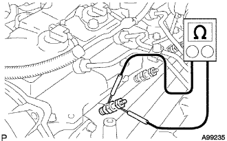
| 32.INSPECT COMMON RAIL ASSEMBLY (FUEL PRESSURE SENSOR) |
 |
Disconnect the F9 sensor connector.
Measure the resistance of the sensor.
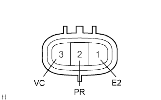
| Tester Connection | Specified Condition |
| 1 (E2) - 2 (PR) | 3 kΩ or less |
| 2 (PR) - 3 (VC) | 16.4 kΩ or less |
|
| ||||
| OK | ||
| ||
