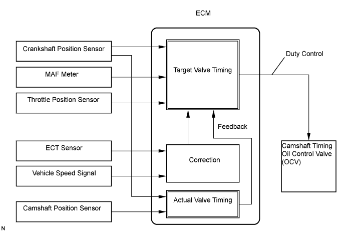
DTC    P0010    Camshaft Position "A" Actuator Circuit (Bank 1)

DTC    P0020    Camshaft Position "A" Actuator Circuit (Bank 2)

for Preparation Click here


DESCRIPTION

The Variable Valve Timing (VVT) system includes the ECM, Oil Control Valve (OCV) and VVT controller. The ECM sends a target "duty-cycle" control signal to the OCV. This control signal, applied to the OCV, regulates the oil pressure supplied to the VVT controller. Camshaft timing control is performed based on engine operation conditions such as intake air volume, throttle position and engine coolant temperature.
The ECM controls the OCV based on signals from several sensors. The VVT controller regulates the intake camshaft angle using oil pressure through the OCV. As a result, the relative position between the camshaft and crankshaft is optimized, the engine torque and fuel economy improve, and the exhaust emissions decrease. The ECM detects the actual valve timing using signals from the camshaft position sensor and crankshaft position sensor. The ECM performs feedback control and verifies target valve timing.

A103843E02


DTC No.
DTC Detection Condition
Trouble Area
P0010
Open or short in oil control valve circuit (bank 1)
(1 trip detection logic)
  1. Open or short in oil control valve circuit (bank 1)
  2. OCV (bank 1)
  3. ECM
P0020
Open or short in oil control valve circuit (bank 2)
(1 trip detection logic)
  1. Open or short in oil control valve circuit (bank 2)
  2. OCV (bank 2)
  3. ECM

MONITOR DESCRIPTION

After the ECM sends the "target" duty-cycle signal to the OCV, the ECM monitors the OCV current to establish an "actual" duty-cycle. The ECM detects a malfunction and sets a DTC when the actual duty-cycle ratio varies from the target duty-cycle ratio.
This monitor runs for 1 second (the first second of the engine idle) after the engine is started.

WIRING DIAGRAM


A088003E09


INSPECTION PROCEDURE

HINT:
  1. If DTC P0010 is displayed, check the right bank VVT system circuit.
  2. Bank 1 refers to the bank that includes the No. 1 cylinder.
  3. If DTC P0020 is displayed, check the left bank VVT system circuit.
  4. Bank 2 refers to the bank that does not include the No. 1 cylinder.
  5. Read freeze frame data using the intelligent tester. Freeze frame data records the engine conditions when a malfunctions is detected. When troubleshooting, freeze frame data can help determine if the vehicle was running or stopped, if the engine was warmed up or not, if the air-fuel ratio was lean or rich, and other data from the time the malfunction occurred.

1.PERFORM ACTIVE TEST (OPERATE OCV)
  1. Start and warm up the engine.

  1. Turn the ignition switch OFF.

  1. Connect the intelligent tester to the DLC3.

  1. Turn the ignition switch ON and turn the tester ON.

  1. Enter the following menus: Powertrain / Engine and ECT / Active Test / Activate the VVT System (bank 1) or Control the VVT System (bank 2).

  1. Using the intelligent tester, operate the OCV and check the engine speed.

    OK:
    Tester Operation
    Specified Condition
    OCV is OFF
    Normal engine speed
    OCV is ON
    Roughly idle or engine stall


OK
CHECK FOR INTERMITTENT PROBLEMS
NG


2.INSPECT CAMSHAFT TIMING OIL CONTROL VALVE ASSEMBLY (OCV SIGNAL)
A094633E14
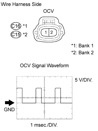
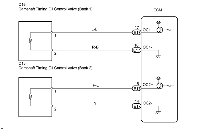
  1. Disconnect the C15 or C16 OCV connectors.

  1. While idling the engine, check the waveform of the OCV connectors using an oscilloscope.

    OK:
    Correct waveform is as shown

    Tester Connection
    C15-2 - C15-1
    C16-2 - C16-1
    Tool Setting
    5 V/DIV., 1 msec./DIV.
    Condition
    Idling


OK
REPLACE CAMSHAFT TIMING OIL CONTROL VALVE ASSEMBLY
NG


3.INSPECT ECM (OCV SIGNAL)
A112441E01
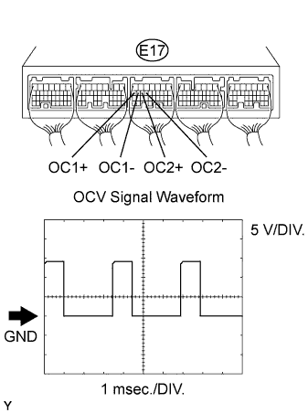
  1. While idling the engine, check the waveform of the ECM connector using an oscilloscope.

    OK:
    Correct waveform is as shown

    Tester Connection
    E17-17 (OC1+) - E17-16 (OC1-)
    E17-15 (OC2+) - E17-14 (OC2-)
    Tool Setting
    5 V/DIV., 1 msec./DIV.
    Condition
    Idling


OK
REPAIR OR REPLACE HARNESS AND CONNECTOR
NG

REPLACE ECM