DTC P0120 Throttle / Pedal Position Sensor / Switch "A" Circuit |
DTC P0122 Throttle / Pedal Position Sensor / Switch "A" Circuit Low Input |
DTC P0123 Throttle / Pedal Position Sensor / Switch "A" Circuit High Input |
DTC P0220 Throttle / Pedal Position Sensor / Switch "B" Circuit |
DTC P0222 Throttle / Pedal Position Sensor / Switch "B" Circuit Low Input |
DTC P0223 Throttle / Pedal Position Sensor / Switch "B" Circuit High Input |
DTC P2135 Throttle / Pedal Position Sensor / Switch "A" / "B" Voltage Correlation |
| DTC No. | DTC Detection Condition | Trouble Area |
| P0120 | Output voltage of VTA1 quickly fluctuates beyond lower and upper malfunction thresholds for 2 seconds (1 trip detection logic) |
|
| P0122 | Output voltage of VTA1 0.2 V or less for 2 seconds (1 trip detection logic) |
|
| P0123 | Output voltage of VTA1 4.8 V or more for 2 seconds (1 trip detection logic) |
|
| P0220 | Output voltage of VTA2 quickly fluctuates beyond lower and upper malfunction thresholds for 2 seconds (1 trip detection logic) |
|
| P0222 | Output voltage of VTA2 0.5 V or less for 2 seconds (1 trip detection logic) |
|
| P0223 | Output voltage of VTA2 4.8 V or more, and VTA1 between 0.2 V and 1.8 V for 2 seconds (1 trip detection logic) |
|
| P2135 | Either condition (a) or (b) met (1 trip detection logic): (a) Difference between output voltages of VTA1 and VTA2 0.02 V or less for 0.5 seconds or more (b) Output voltage of VTA1 0.2 V or less, and VTA2 0.5 V or less, for 0.4 seconds or more |
|
| Tester Display | Accelerator Pedal Fully Released | Accelerator Pedal Fully Depressed |
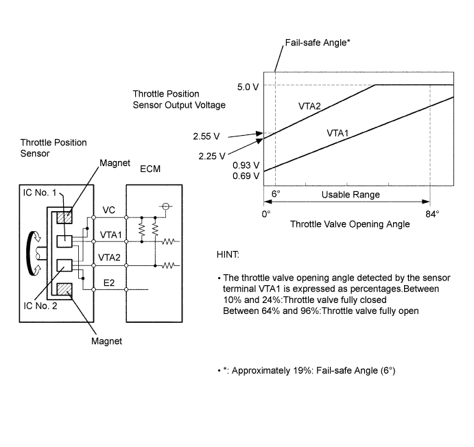
| Throttle Position | 10 to 24% | 64 to 96% |
| Throttle Position No. 2 | 2.1 to 3.1 V | 4.5 to 5.5 V |
| 1.READ DATA LIST (THROTTLE POSITION, THROTTLE POSITION NO. 2) |
Connect the intelligent tester to the DLC3.
Turn the ignition switch ON and turn the tester ON.
Enter the following menus: Powertrain / Engine and ECT / Data List / Throttle Position and Throttle Position No. 2.
Read the values.
| TP (VTA1) When AP Released | TP No. 2 (VTA2) When AP Released | TP (VTA1) When AP Depressed | TP No. 2 (VTA2) When AP Depressed | Suspected Area | Proceed to |
| 0% | 0 to 0.2 V | 0% | 0 to 0.2 V | VC circuit open | A |
| 100% | 4.5 to 5.0 V | 100% | 4.5 to 5.0 V | E2 circuit open | A |
| 0 or 100% | 2.1 to 3.1 V (fail-safe) | 0 or 100% | 2.1 to 3.1 V (fail-safe) | VTA1 circuit open or ground short | A |
| 10 to 24% (fail-safe) | 0 to 0.2 V, or 4.5 to 5.0 V | 10 to 24% (fail-safe) | 0 to 0.2 V, or 4.5 to 5.5 V | VTA2 circuit open or ground short | A |
| 10 to 24% | 2.1 to 3.1 V | 64 to 96% (not fail-safe) | 4.5 to 5.0 V (not fail-safe) | Throttle position sensor circuit is normal | B |
|
| ||||
| A | |
| 2.CHECK WIRE HARNESS (THROTTLE POSITION SENSOR - ECM) |
 |
Disconnect the T1 throttle body connector.
Disconnect the E15 ECM connector.
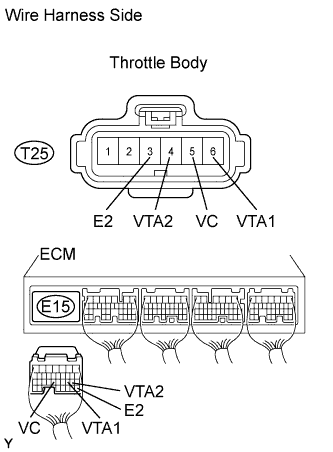
Measure the resistance of the wire harness side connectors.
| Tester Connection | Specified Condition |
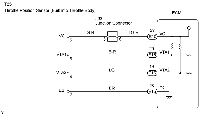
| T25-5 (VC) - E15-23 (VC) | Below 1 Ω |
| T25-6 (VTA1) - E15-20 (VTA1) | Below 1 Ω |
| T25-4 (VTA2) - E15-19 (VTA2) | Below 1 Ω |
| T25-3 (E2) - E15-28 (E2) | Below 1 Ω |
| T25-5 (VC) or E15-23 (VC) -Body ground | 10 kΩ or higher |
| T25-6 (VTA1) or E15-20 (VTA1) - Body ground | 10 kΩ or higher |
| T25-4 (VTA2) or E15-19 (VTA2) - Body ground | 10 kΩ or higher |
|
| ||||
| OK | |
| 3.INSPECT ECM (VC VOLTAGE) |
 |
Disconnect the throttle body connector.
Turn the ignition switch ON.
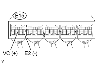
Measure the voltage of the ECM connector.
| Tester Connection | Specified Condition |
| E15-23 (VC) - E15-28 (E2) | 4.5 to 5.0 V |
|
| ||||
| OK | |
| 4.REPLACE THROTTLE BODY |
| NEXT | |
| 5.CHECK IF DTC OUTPUT RECURS (THROTTLE POSITION SENSOR DTCS) |
Clear the DTCs (Click here).
Start the engine.
Idle engine for 15 seconds or more.
Connect the intelligent tester to the DLC3.
Turn the tester ON.
Enter the following menus: Powertrain / Engine and ECT / DTC.
Read the DTCs.
| Display (DTC output) | Proceed to |
| P0120, P0122, P0123, P0220, P0222, P0223 and/or P2135 | A |
| No output | B |
|
| ||||
| A | ||
| ||
