ECD SYSTEM > Engine Difficult to Start or Stalling |
| 1.CHECK OUTPUT DTC (RELATED TO ENGINE) |
Connect the intelligent tester to the DLC3.
Turn the ignition switch ON and turn the intelligent tester ON.
Enter the following menus: Powertrain / Engine / DTC.
Read DTCs.
| Display (DTC Output) | Proceed to |
| No output | A |
| DTCs related to engine (Click here) | B |
|
| ||||
| A | |
| 2.CHECK FUEL FILTER ASSEMBLY |
Check that the fuel filter is not clogged.
|
| ||||
| OK | |
| Go to step 2 |
| 3.CHECK ENGINE CRANKING CONDITION |
Check the engine cranking condition.
Compare the cranking condition with that of a normal engine of the same model, and carefully check if there is any difference between them.
|
| ||||
| OK | |
| 4.READ VALUE OF FUEL PRESSURE SENSOR |
Connect the intelligent tester to the DLC3.
Turn the ignition switch ON and turn the intelligent tester ON.
Enter the following menus: Powertrain / Engine / Data List / Fuel Press.
Read the values.
| Item | Inspection Condition | Reference Value |
| Fuel Press | Cranking, and engine coolant temperature 0°C (32°F) or more | 32 MPa |
|
| ||||
| OK | |
| 5.CHECK IF INITIAL COMBUSTION OCCURS |
Check if initial combustion occurs.
| Result | Proceed To |
| No initial combustion with cold engine | A |
| No initial combustion with hot engine | B |
| Initial combustion occurs | C |
|
| ||||
|
| ||||
| A | |
| 6.CHECK GLOW INDICATOR LIGHTING TIME AND AFTER GLOW TIME |
Check the lighting duration of glow indicator light (Click here).
|
| ||||
| OK | |
| 7.READ VALUE OF FUEL PRESSURE SENSOR |
Connect the intelligent tester to the DLC3.
Start the engine and turn the intelligent tester ON.
Enter the following menus: Powertrain / Engine / Data List / Fuel Press.
Check that the internal fuel pressure of the common rail is within the specification below.
| Engine Speed | Fuel Pressure |
| Idling | Approximately 30 to 40 MPa |
| 3,000 rpm (No engine load) | Approximately 50 to 70 MPa |
|
| ||||
| OK | |
| 8.CHECK AIR INTAKE SYSTEM AND EXHAUST SYSTEM |
Remove the air cleaner filter.
Inspect the EGR valve operation.
Start the engine and warm it up.
When the engine is idling and the vacuum hose is disconnected from the EGR valve, check that clicking sounds are emitted from the EGR valve.
Inspect the throttle valve operation.
Start the engine.
Check if the throttle valve fully opens when accelerating the engine speed.
|
| ||||
| OK | |
| 9.READ VALUE OF FUEL PRESSURE SENSOR AND INJECTOR |
Connect the intelligent tester to the DLC3.
Start the engine and turn the intelligent tester ON.
Enter the following menus: Powertrain / Engine / Data List.
Select the following menu items in order and read the values.
| Item | Engine Speed* | Reference Value |
| Fuel Press | Idling | 30 to 40 MPa |
| Fuel Press | 2,000 rpm (No engine load) | 40 to 50 MPa |
| Fuel Press | 3,000 rpm (No engine load) | 50 to 70 MPa |
| Injection Volume | Idling | 5 to 12 mm3
|
| Injection Volume | 2,000 rpm (No engine load) | 5 to 12 mm3
|
| Injection Volume | 3,000 rpm (No engine load) | 7 to 14 mm3
|
|
| ||||
| OK | |
| 10.INSPECT CYLINDER COMPRESSION PRESSURE |
|
| ||||
| OK | |
| 11.CHECK WIRE HARNESS (INJECTOR - EDU) |
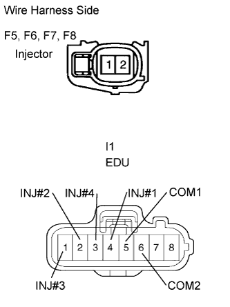 |
Disconnect the F5, F6, F7 and F8 injector connectors.
Disconnect the I1 EDU connector.
Measure the resistance of the wire harness side connectors.
| Tester Connection | Specified Condition. |
| F5-1 - I1-4 (INJ#1) | Below 1 Ω |
| F6-1 - I1-2 (INJ#2) | Below 1 Ω |
| F7-1 - I1-1 (INJ#3) | Below 1 Ω |
| F8-1 - I1-3 (INJ#4) | Below 1 Ω |
| F5-2 - I1-5 (COM1) | Below 1 Ω |
| F6-2 - I1-6 (COM2) | Below 1 Ω |
| F7-2 - I1-6 (COM2) | Below 1 Ω |
| F8-2 - I1-5 (COM1) | Below 1 Ω |
| F5-1 or I1-4 (INJ#1) - Body ground | 10 kΩ or higher |
| F6-1 or I1-2 (INJ#2) - Body ground | 10 kΩ or higher |
| F7-1 or I1-1 (INJ#3) - Body ground | 10 kΩ or higher |
| F8-1 or I1-3 (INJ#4) - Body ground | 10 kΩ or higher |
| F5-2 or I1-5 (COM1) - Body ground | 10 kΩ or higher |
| F6-2 or I1-6 (COM2) - Body ground | 10 kΩ or higher |
| F7-2 or I1-6 (COM2) - Body ground | 10 kΩ or higher |
| F8-2 or I1-5 (COM1) - Body ground | 10 kΩ or higher |
|
| ||||
| OK | |
| 12.PERFORM ACTIVE TEST BY INTELLIGENT TESTER (CONTROL CYLINDER FUEL CUT) |
Connect the intelligent tester to the DLC3.
Start the engine and turn the intelligent tester ON.
Enter the following menus: Powertrain / Engine / Active Test / Control the Cylinder#1, #2, #3 and #4 Fuel Cut.
Check the engine idling condition while the fuel injection of each cylinder is cut using the intelligent tester.
| Engine Idling Condition | Proceed to |
| Becomes unstable | A |
| Does not change | B |
|
| ||||
| A | ||
| ||
| 13.CHECK IF FUEL IS BEING SUPPLIED TO SUPPLY PUMP |
Disconnect the inlet hose from the supply pump.
Operate the priming pump and check that the fuel is being supplied to the supply pump.
|
| ||||
| NG | ||
| ||
| 14.CHECK ECM (THW VOLTAGE) |
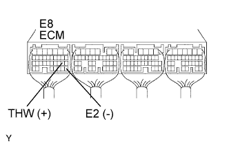 |
Start the engine.
Measure the voltage of the ECM connector.
| Tester Connection | Condition | Specified Condition |
| E8-19 (THW) - E8-28 (E2) | Idling, engine coolant temperature between 60 and 120°C (140 and 248°F) | 0.2 to 1.0 V |
|
| ||||
| OK | |
| 15.CHECK ECM (NE SIGNAL) |
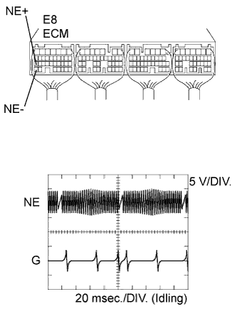 |
While idling the engine, check the waveform between the specified terminals of the E7 ECM connector using an oscilloscope.
| Tester Connection | Specified Condition |
| E8-27 (NE+) - E8-34 (NE-) | Correct waveform is shown |
| Tool Setting | Condition |
| 5 V/DIV., 20 msec./DIV. | Idling with warm engine |
|
| ||||
| OK | |
| 16.CHECK WIRE HARNESS (STARTER RELAY - ECM) |
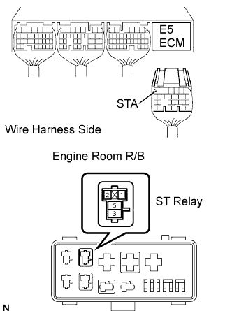 |
Disconnect the E5 ECM connector.
Remove the ST relay from the engine room R/B.
Measure the resistance of the wire harness side connectors.
| Tester Connection | Specified Condition |
| R/B ST relay terminal 1 - E4-7 (STA) | Below 1 Ω |
| R/B ST relay terminal 1 or E4-7 (STA) - Body ground | 10 kΩ or higher |
|
| ||||
| OK | |
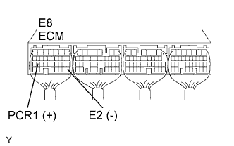
| 17.CHECK ECM (PCR1 VOLTAGE) |
 |
Start the engine.
Measure the voltage of the ECM connector.
| Tester Connection | Condition | Specified Condition |
| E8-26 (PCR1) - E8-28 (E2) | Idling | 1.8 to 2.1 V |
|
| ||||
| OK | ||
| ||
| 18.INSPECT ENGINE COOLANT TEMPERATURE SENSOR |
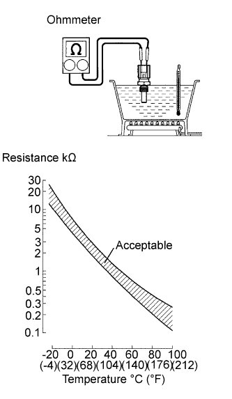 |
Remove the sensor.
Measure the resistance of the sensor
| Connection | Specified Condition |
| 20°C (68°F) | 2.32 to 2.59 kΩ |
| 80°C (176°F) | 0.310 to 0.326 kΩ |
|
| ||||
| OK | ||
| ||
| 19.INSPECT CRANKSHAFT POSITION SENSOR |
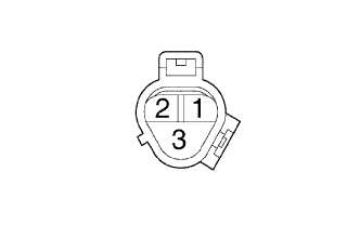 |
Disconnect the C4 sensor connector.
Measure the resistance between terminals 1 and 2.
| Tester Connection | Condition | Specified Condition |
| 1 - 2 | Cold | 1,630 to 2,740 Ω |
| 1 - 2 | Hot | 2,065 to 3,225 Ω |
|
| ||||
| OK | ||
| ||
| 20.INSPECT COMMON RAIL ASSEMBLY (FUEL PRESSURE SENSOR) |
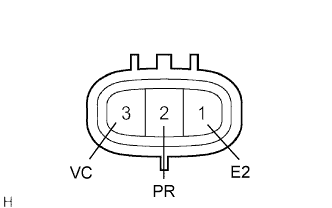 |
Disconnect the F9 sensor connector.
Measure the resistance of the sensor.
| Tester Connection | Specified Condition |
| F8-2 (PC) - F8-1 (E2) | 3 kΩ or less |
| F8-2 (PC) - F8-3 (VC) | 16.4 kΩ or less |
|
| ||||
| OK | |
| 21.CHECK WIRE HARNESS (FUEL PRESSURE SENSOR - ECM) |
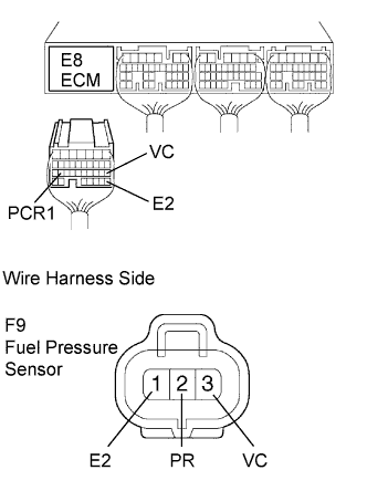 |
Disconnect the E8 ECM connector.
Disconnect the F9 sensor connector.
Measure the resistance of the wire harness side connectors.
| Tester Connection | Specified Condition |
| E8-26 (PCR1) - F9-2 (PR) | Below 1 Ω |
| E8-18 (VC) - F9-3 (VC) | Below 1 Ω |
| E8-28 (E2) - F9-1 (E2) | Below 1 Ω |
| E8-26 (PCR1) or F9-2 (PR) - Body ground | 10 kΩ or higher |
| E8-18 (VC) or F9-3 (VC) - Body ground | 10 kΩ or higher |
| E8-28 (E2) or F9-1 (E2) - Body ground | 10 kΩ or higher |
|
| ||||
| OK | |
| 22.REPLACE ECM |
|
| ||||
| OK | ||
| ||
