ECD SYSTEM > Engine Difficult to Start or Stalling |
| 1.CHECK OUTPUT DTC (RELATED TO ENGINE) |
Connect the intelligent tester to the DLC3.
Turn the ignition switch ON and turn the intelligent tester ON.
Enter the following menus: Powertrain / Engine / DTC.
Read DTCs.
| Display (DTC Output) | Proceed to |
| No output | A |
| DTCs related to engine (Click here) | B |
|
| ||||
| A | |
| 2.CHECK FUEL FILTER ASSEMBLY |
Check that the fuel filter is not clogged.
|
| ||||
| OK | |
| Go to step 2 |
| 3.CHECK ENGINE CRANKING CONDITION |
Check the engine cranking condition.
Compare the cranking condition with that of a normal engine of the same model, and carefully check if there is any difference between them.
|
| ||||
| OK | |
| 4.READ VALUE OF FUEL PRESSURE SENSOR |
Connect the intelligent tester to the DLC3.
Turn the ignition switch ON and turn the intelligent tester ON.
Enter the following menus: Powertrain / Engine / Data List / Fuel Press.
Read the values.
| Item | Inspection Condition | Reference Value |
| Fuel Press | Cranking, and engine coolant temperature 0°C (32°F) or more | 20 to 55 MPa |
|
| ||||
| OK | |
| 5.CHECK IF INITIAL COMBUSTION OCCURS |
Check if initial combustion occurs.
| Result | Proceed To |
| No initial combustion with cold engine | A |
| No initial combustion with hot engine | B |
| Initial combustion occurs | C |
|
| ||||
|
| ||||
| A | |
| 6.CHECK GLOW INDICATOR LIGHTING TIME AND AFTER GLOW TIME |
Check the lighting duration of glow indicator light (Click here).
|
| ||||
| OK | |
| 7.READ VALUE OF FUEL PRESSURE SENSOR |
Connect the intelligent tester to the DLC3.
Start the engine and turn the intelligent tester ON.
Enter the following menus: Powertrain / Engine / Data List / Fuel Press.
Check that the internal fuel pressure of the common rail is within the specification below.
| Engine Speed | Fuel Pressure |
| Idling | Approximately 25 to 35 MPa |
| 3,000 rpm (No engine load) | Approximately 35 to 55 MPa |
|
| ||||
| OK | |
| 8.CHECK AIR INTAKE SYSTEM AND EXHAUST SYSTEM |
Remove the air cleaner filter.
Inspect the throttle valve operation.
Start the engine.
Check if the throttle valve fully opens when accelerating the engine speed.
|
| ||||
| OK | |
| 9.READ VALUE OF FUEL PRESSURE SENSOR AND INJECTOR |
Connect the intelligent tester to the DLC3.
Start the engine and turn the intelligent tester ON.
Enter the following menus: Powertrain / Engine / Data List.
Select the following menu items in order and read the values.
| Item | Engine Speed* | Reference Value |
| Fuel Press | Idling | 25 to 35 MPa |
| Fuel Press | 2,000 rpm (No engine load) | 25 to 35 MPa |
| Fuel Press | 3,000 rpm (No engine load) | 35 to 45 MPa |
| Injection Volume | Idling | 3 to 10 mm3
|
| Injection Volume | 2,000 rpm (No engine load) | 3 to 10 mm3
|
| Injection Volume | 3,000 rpm (No engine load) | 4 to 12 mm3
|
|
| ||||
| OK | |
| 10.INSPECT CYLINDER COMPRESSION PRESSURE |
|
| ||||
| OK | |
| 11.CHECK HARNESS AND CONNECTOR (INJECTOR - EDU) |
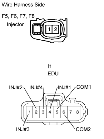 |
Disconnect the F5, F6, F7 and F8 injector connector.
Disconnect the I1 EDU connector.
Measure the resistance of the wire harness side connectors.
| Tester Connection | Specified Condition. |
| F5-1 - I1-4 (INJ#1) | Below 1 Ω |
| F6-1 - I1-2 (INJ#2) | Below 1 Ω |
| F7-1 - I1-1 (INJ#3) | Below 1 Ω |
| F8-1 - I1-3 (INJ#4) | Below 1 Ω |
| F5-2 - I1-5 (COM1) | Below 1 Ω |
| F6-2 - I1-6 (COM2) | Below 1 Ω |
| F7-2 - I1-6 (COM2) | Below 1 Ω |
| F8-2 - I1-5 (COM1) | Below 1 Ω |
| F5-1 or I1-4 (INJ#1) - Body ground | 10 kΩ or higher |
| F6-1 or I1-2 (INJ#2) - Body ground | 10 kΩ or higher |
| F7-1 or I1-1 (INJ#3) - Body ground | 10 kΩ or higher |
| F8-1 or I1-3 (INJ#4) - Body ground | 10 kΩ or higher |
| F5-2 or I1-5 (COM1) - Body ground | 10 kΩ or higher |
| F6-2 or I1-6 (COM2) - Body ground | 10 kΩ or higher |
| F7-2 or I1-6 (COM2) - Body ground | 10 kΩ or higher |
| F8-2 or I1-5 (COM1) - Body ground | 10 kΩ or higher |
|
| ||||
| OK | |
| 12.PERFORM ACTIVE TEST BY INTELLIGENT TESTER (CONTROL CYLINDER FUEL CUT) |
Connect the intelligent tester to the DLC3.
Start the engine and turn the intelligent tester ON.
Enter the following menus: Powertrain / Engine / Active Test / Control the Cylinder#1, #2, #3 and #4 Fuel Cut.
Check the engine idling condition while the fuel injection of each cylinder is cut using the intelligent tester.
| Engine Idling Condition | Proceed to |
| Becomes unstable | A |
| Does not change | B |
|
| ||||
| A | ||
| ||
| 13.CHECK IF FUEL IS BEING SUPPLIED TO SUPPLY PUMP |
Disconnect the inlet hose from the supply pump.
Operate the priming pump and check that the fuel is being supplied to the supply pump.
|
| ||||
| NG | ||
| ||
| 14.CHECK ECM TERMINAL VOLTAGE (THW TERMINAL) |
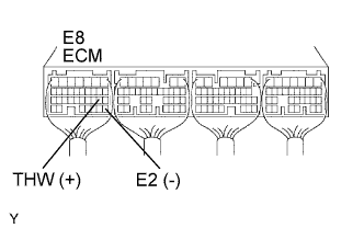 |
Start the engine.
Measure the voltage of the ECM connector.
| Tester Connection | Condition | Specified Condition |
| E8-19 (THW) - E8-28 (E2) | Idling, engine coolant temperature between 60 and 120°C (140 and 248°F) | 0.2 to 1.0 V |
|
| ||||
| OK | |
| 15.CHECK ECM TERMINAL VOLTAGE (NE+ AND NE- TERMINALS) |
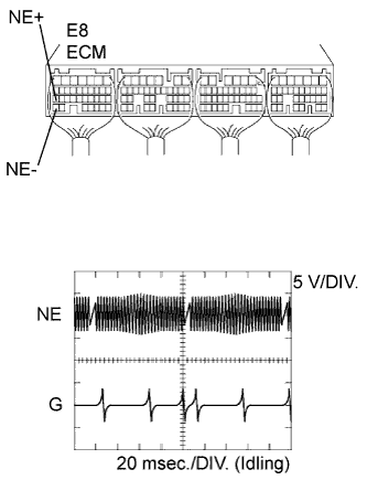 |
While idling the engine, check the waveform between the specified terminals of the E7 ECM connector using an oscilloscope.
| Tester Connection | Specified Condition |
| E8-27 (NE+) - E8-34 (NE-) | Correct waveform is shown |
| Tool Setting | Condition |
| 5 V/DIV., 20 msec./DIV. | Idling with warm engine |
|
| ||||
| OK | |
| 16.CHECK HARNESS AND CONNECTOR (STARTER RELAY - ECM) |
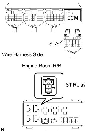 |
Disconnect the E5 ECM connector.
Remove the ST relay from the engine room R/B.
Measure the resistance of the wire harness side connectors.
| Tester Connection | Specified Condition |
| R/B ST relay terminal 1 - E4-7 (STA) | Below 1 Ω |
| R/B ST relay terminal 1 or E4-7 (STA) - Body ground | 10 kΩ or higher |
|
| ||||
| OK | |
| 17.CHECK ECM TERMINAL VOLTAGE (PCR1 TERMINAL) |
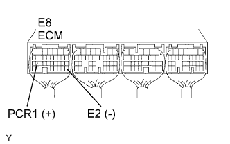 |
Start the engine.
Measure the voltage of the ECM connector.
| Tester Connection | Condition | Specified Condition |
| E8-26 (PCR1) - E8-28 (E2) | Idling | 1.8 to 2.1 V |
|
| ||||
| OK | ||
| ||
| 18.INSPECT ENGINE COOLANT TEMPERATURE SENSOR |
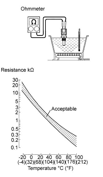 |
Remove the sensor.
Measure the resistance of the sensor
| Connection | Specified Condition |
| 20°C (68°F) | 2 2.32 to 2.59 kΩ |
| 80°C (176°F) | 0.310 to 0.326 kΩ |
|
| ||||
| OK | ||
| ||
| 19.INSPECT CRANKSHAFT POSITION SENSOR |
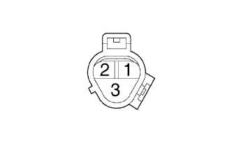 |
Disconnect the C4 sensor connector.
Measure the resistance between terminals 1 and 2.
| Tester Connection | Condition | Specified Condition |
| 1 - 2 | Cold | 1,630 to 2,740 Ω |
| 1 - 2 | Hot | 2,065 to 3,225 Ω |
|
| ||||
| OK | ||
| ||
| 20.INSPECT COMMON RAIL ASSEMBLY (FUEL PRESSURE SENSOR) |
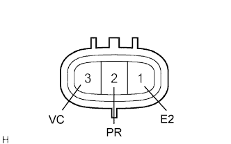 |
Disconnect the F9 sensor connector.
Measure the resistance of the sensor.
| Tester Connection | Specified Condition |
| F8-2 (PC) - F8-1 (E2) | 3 kΩ or less |
| F8-2 (PC) - F8-3 (VC) | 16.4 kΩ or less |
|
| ||||
| OK | |
| 21.CHECK HARNESS AND CONNECTOR (FUEL PRESSURE SENSOR - ECM) |
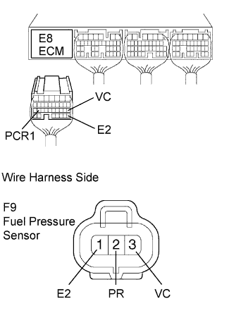 |
Disconnect the E8 ECM connector.
Disconnect the F9 sensor connector.
Measure the resistance of the wire harness side connectors.
| Tester Connection | Specified Condition |
| E8-26 (PCR1) - F9-2 (PR) | Below 1 Ω |
| E8-18 (VC) - F9-3 (VC) | Below 1 Ω |
| E8-28 (E2) - F9-1 (E2) | Below 1 Ω |
| E8-26 (PCR1) or F9-2 (PR) - Body ground | 10 kΩ or higher |
| E8-18 (VC) or F9-3 (VC) - Body ground | 10 kΩ or higher |
| E8-28 (E2) or F9-1 (E2) - Body ground | 10 kΩ or higher |
|
| ||||
| OK | |
| 22.REPLACE ECM |
|
| ||||
| OK | ||
| ||
