ECD SYSTEM > Black Smoke Emitted |
| 1.CHECK OUTPUT DTC (RELATED TO ENGINE) |
Connect the intelligent tester to the DLC3.
Turn the ignition switch ON and turn the intelligent tester ON.
Enter the following menus: Powertrain / Engine / DTC.
Read the DTCs.
| Display (DTC Output) | Proceed to |
| No output | A |
| DTCs related to engine (Click here) | B |
|
| ||||
| A | |
| 2.READ VALUE OF INJECTOR ASSEMBLY (INJECTION VOLUME AND INJECTION FEED BACK VAL #1 TO #4) |
Connect the intelligent tester to the DLC3.
Start the engine and turn the intelligent tester ON.
Enter the following menus: Powertrain / Engine / Data List.
Select the following menu items in order and read the values.
| Item | Engine Speed* | Reference Value |
| Injection Volume | Idling (No engine load) | 5 to 12 mm3
|
| Injection Feedback Val #1 | Idling (No engine load) | -3.0 to 3.0 mm3
|
| Injection Feedback Val #2 | Idling (No engine load) | -3.0 to 3.0 mm3
|
| Injection Feedback Val #3 | Idling (No engine load) | -3.0 to 3.0 mm3
|
| Injection Feedback Val #4 | Idling (No engine load) | -3.0 to 3.0 mm3
|
|
| ||||
| OK | |
| 3.PERFORM ENGINE RPM ACCELERATION |
Accelerate the engine speed to the maximum rpm with no load 20 times.
Check the volume of black smoke in the exhaust gas.
| Result | Proceed to |
| Black smoke is not present | OK |
| Black smoke remains in the exhaust gas | NG |
|
| ||||
| NG | |
| 4.CHECK AIR INTAKE SYSTEM AND EXHAUST SYSTEM |
Remove the air cleaner filter.
Inspect the EGR valve operation.
Start the engine and warm it up.
When the engine is idling and the vacuum hose is disconnected from the EGR valve, check that clicking sounds are emitted from the EGR valve.
Inspect the throttle valve operation.
Start the engine.
Check if the throttle valve fully opens when accelerating the engine speed.
|
| ||||
| OK | |
| 5.READ VALUE OF MASS AIR FLOW RATE |
Disconnect the throttle control motor.
Disconnect the EGR E-VRV connector
Connect the intelligent tester to the DLC3.
Start the engine and turn the tester ON.
Enter the following menus: Powertrain / Engine / Data List / MAF.
Read the values.
| Engine Speed Condition | Air Flow Rate |
| 750 rpm | 5 to 12 gm/s |
|
| ||||
| OK | |
| 6.CHECK TURBOCHARGING PRESSURE |
Check the turbocharger pressure (Click here).
|
| ||||
| OK | |
| 7.PERFORM ACTIVE TEST BY FUEL PRESSURE SENSOR AND INJECTOR ASSEMBLY |
Connect the intelligent tester to the DLC3.
Start the engine and turn the intelligent tester ON.
Enter the following menus: Powertrain / Engine / Data List.
Select the following menu items in order and read the values.
| Item | Engine Speed* | Reference Value |
| Fuel Pressure | Idling | 30 to 40 MPa |
| Fuel Pressure | 2,000 rpm (no engine load) | 40 to 50 MPa |
| Fuel Pressure | 3,000 rpm (no engine load) | 50 to 70 MPa |
| Injection Volume | Idling | 5 to 12 mm3
|
| Injection Volume | 2,000 rpm (no engine load) | 5 to 12 mm3
|
| Injection Volume | 3,000 rpm (no engine load) | 7 to 14 mm3
|
| Main Injection | Idling | 530 to 730 μs |
| Pilot 1 Injection | Idling | 380 to 480 μs |
| Injection Feedback Val #1 | Idling | -3.0 to 3.0 mm3
|
| Injection Feedback Val #2 | Idling | -3.0 to 3.0 mm3
|
| Injection Feedback Val #3 | Idling | -3.0 to 3.0 mm3
|
| Injection Feedback Val #4 | Idling | -3.0 to 3.0 mm3
|
| Result | Proceed to |
| Within reference value | A |
| One of Injection Feedback Val #1 to #4 is not within reference value | B |
| Other result | C |
|
| ||||
|
| ||||
| A | |
| 8.INSPECT CYLINDER COMPRESSION PRESSURE |
Check the cylinder compression pressure (Click here).
|
| ||||
| OK | |
| 9.CHECK WIRE HARNESS (INJECTOR ASSEMBLY - EDU) |
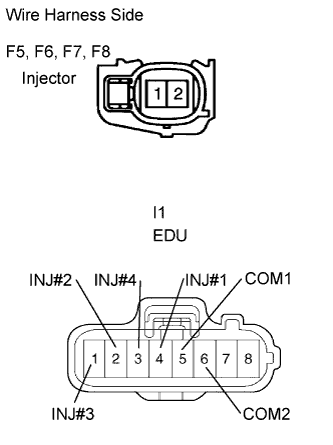 |
Disconnect the F5, F6, F7 and F8 injector connectors.
Disconnect the I1 EDU connector.
Measure the resistance of the wire harness side connectors.
| Tester Connection | Specified Condition |
| F5-1 - I1-4 (INJ#1) | Below 1 Ω |
| F6-1 - I1-2 (INJ#2) | Below 1 Ω |
| F7-1 - I1-1 (INJ#3) | Below 1 Ω |
| F8-1 - I1-3 (INJ#4) | Below 1 Ω |
| F5-2 - I1-5 (COM1) | Below 1 Ω |
| F6-2 - I1-6 (COM2) | Below 1 Ω |
| F7-2 - I1-6 (COM2) | Below 1 Ω |
| F8-2 - I1-5 (COM1) | Below 1 Ω |
| F5-1 or I1-4 (INJ#1) - Body ground | 10 kΩ or higher |
| F6-1 or I1-2 (INJ#2) - Body ground | 10 kΩ or higher |
| F7-1 or I1-1 (INJ#3) - Body ground | 10 kΩ or higher |
| F8-1 or I1-3 (INJ#4) - Body ground | 10 kΩ or higher |
| F5-2 or I1-5 (COM1) - Body ground | 10 kΩ or higher |
| F6-2 or I1-6 (COM2) - Body ground | 10 kΩ or higher |
| F7-2 or I1-6 (COM2) - Body ground | 10 kΩ or higher |
| F8-2 or I1-5 (COM1) - Body ground | 10 kΩ or higher |
|
| ||||
| OK | |
| 10.PERFORM ACTIVE TEST BY INTELLIGENT TESTER (CONTROL THE CYLINDER FUEL CUT) |
Connect the intelligent tester to the DLC3.
Start the engine and turn the intelligent tester ON.
Enter the following menus: Powertrain / Engine / Active Test / Control the Cylinder#1, #2, #3 and #4 Fuel Cut.
Check the engine idling condition while the fuel injection of each cylinder is cut using the intelligent tester.
| Engine Idling Condition | Proceed To |
| Becomes unstable | A |
| Does not change | B |
|
| ||||
| A | ||
| ||
| 11.CHECK ECM (THW VOLTAGE) |
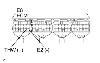 |
Start the engine.
Measure the voltage of the ECM connector.
| Tester Connection | Condition | Specified Condition |
| E8-19 (THW) - E8-28 (E2) | Idling, engine coolant temperature between 60 and 120°C (140 and 248°F) | 0.2 to 1.0 V |
|
| ||||
| OK | |
| 12.CHECK ECM (PIM VOLTAGE) |
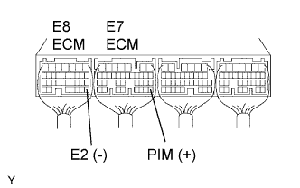 |
Turn the ignition switch ON.
Measure the voltage of the ECM connectors.
| Tester Connection | Condition | Specified Condition |
| E7-28 (PIM) - E8-28 (E2) | Applied negative pressure of 40 kPa (300 mmHg, 11.8 in.Hg) | 1.3 to 1.9 V |
| E7-28 (PIM) - E8-28 (E2) | Same as atmospheric pressure | 2.4 to 3.1 V |
| E7-28 (PIM) - E8-28 (E2) | Applied positive pressure of 69 kPa (518 mmHg, 20.4 in.Hg) | 3.7 to 4.3 V |
|
| ||||
| OK | |
| 13.CHECK ECM (NE SIGNAL) |
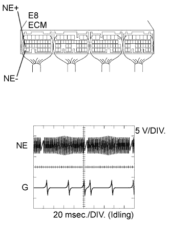 |
While idling the engine, check the waveform of the ECM connector using an oscilloscope.
| Tester Connection | Specified Condition |
| E8-27 (NE+) - E8-34 (NE-) | Correct waveform is shown |
| Tool Setting | Condition |
| 5 V/DIV., 20 msec./DIV. | Idling with warm engine |
|
| ||||
| OK | |
| 14.CHECK ECM (VPA, VPA2 VOLTAGE) |
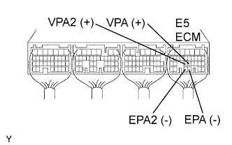 |
Turn the ignition switch ON.
Measure the voltage of the ECM connector.
| Tester Condition | Accelerator Pedal Condition | Specified Condition |
| E5-22 (VPA) - E5-28 (EPA) | Released | 0.6 to 1.0 V |
| E5-22 (VPA) - E5-28 (EPA) | Depressed | 2.9 to 4.2 V |
| E5-23 (VPA2) - E5-29 (EPA2) | Released | 1.4 to 1.8 V |
| E5-23 (VPA2) - E5-29 (EPA2) | Depressed | 3.7 to 5.0 V |
|
| ||||
| OK | |
| 15.CHECK ECM (THA VOLTAGE) |
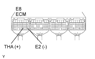 |
Start the engine.
Measure the voltage of the ECM connector.
| Tester Connection | Condition | Specified Condition |
| E8-31 (THA) - E8-28 (E2) | Idling, intake air temperature at 20°C (68°F) | 0.5 to 3.4 V |
|
| ||||
| OK | |
| 16.CHECK ECM (PCR1 VOLTAGE) |
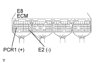 |
Start the engine.
Measure the voltage of the ECM connector.
| Tester Connection | Condition | Specified Condition |
| E8-26 (PCR1) - E8-28 (E2) | Idling | 1.3 to 1.8 V |
|
| ||||
| OK | ||
| ||
| 17.INSPECT ENGINE COOLANT TEMPERATURE SENSOR |
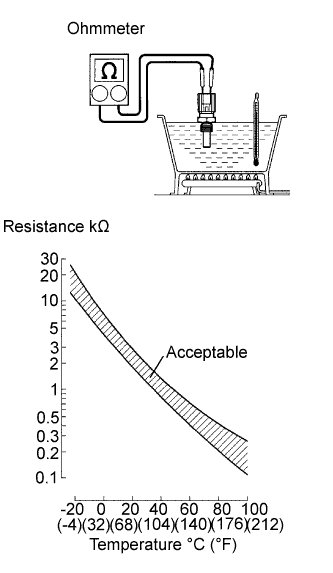 |
Remove the sensor.
Measure the resistance of the sensor
| Connection | Specified Condition |
| 20°C (68°F) | 2.32 to 2.59 kΩ |
| 80°C (176°F) | 0.310 to 0.326 kΩ |
|
| ||||
| OK | ||
| ||
| 18.CHECK WIRE HARNESS (MANIFOLD ABSOLUTE PRESSURE SENSOR - ECM) |
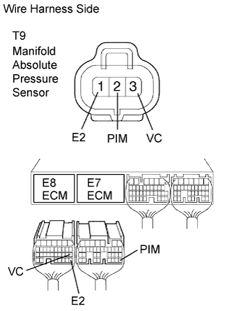 |
Disconnect the T9 sensor connector.
Disconnect the E7 and E8 ECM connectors.
Measure the resistance of the wire harness side connectors.
| Tester Connection | Specified Condition |
| T9-2 (PIM) - E7-28 (PIM) | Below 1 Ω |
| T9-3 (VC) - E8-18 (VC) | Below 1 Ω |
| T9-1 (E2)) - E8-28 (E2) | Below 1 Ω |
| T9-2 (PIM) or E7-28 (PIM) - Body ground | 10 kΩ or higher |
| T9-3 (VC) or E8-18 (VC) - Body ground | 10 kΩ or higher |
| T9-1 (E2) or E8-28 (E2) - Body ground | 10 kΩ or higher |
|
| ||||
| OK | ||
| ||
| 19.INSPECT CRANKSHAFT POSITION SENSOR |
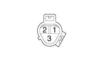 |
Disconnect the C4 sensor connector.
Measure the resistance of the sensor.
| Tester Connection | Condition | Specified Condition |
| 1 - 2 | Cold | 1,630 to 2,740 Ω |
| 1 - 2 | Hot | 2,065 to 3,225 Ω |
|
| ||||
| OK | ||
| ||
| 20.CHECK WIRE HARNESS (ACCELERATOR PEDAL POSITION SENSOR - ECM) |
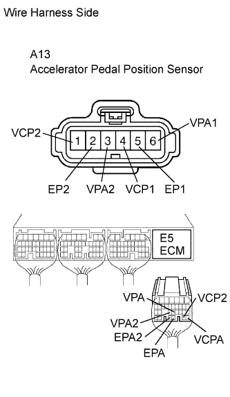 |
Disconnect the A13 sensor connector.
Disconnect the E5 ECM connector.
Measure the resistance of the wire harness side connectors.
| Tester Connection | Specified Condition |
| A13-1 (VCP2) - E5-27 (VCP2) A13-2 (EPA2) - E5-29 (EPA2) A13-3 (VPA2) - E5-23 (VPA2) A13-4 (VCP1) - E5-26 (VCPA) A13-5 (EP1) - E5-28 (EPA) A13-6 (VPA1) - E5-22 (VPA) | Below 1 Ω |
| A13-1 (VCP2) or E5-27 (VCP2) - Body ground A13-2 (EPA2) or E5-29 (EP2) - Body ground A13-3 (VPA2) or E5-23 (VPA2) - Body ground A13-4 (VCP1) or E5-26 (VCPA) - Body ground A13-5 (EP1) or E5-28 (EPA) - Body ground A13-6 (VPA1) or E5-22 (VPA) - Body ground | 10 kΩ or higher |
|
| ||||
| OK | ||
| ||
| 21.INSPECT INTAKE AIR TEMPERATURE SENSOR |
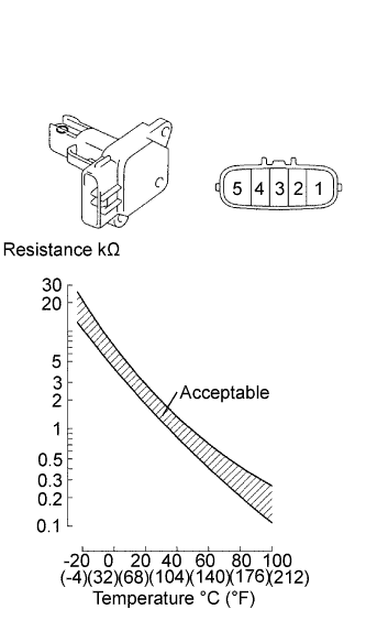 |
Remove the MAF meter.
Measure the resistance of the sensor.
| Tester Connection | Condition | Specified Condition |
| 4 - 5 | -20°C (-4°F) | 13.6 to 18.4 kΩ |
| 4 - 5 | 20°C (68°F) | 2.21 to 2.69 kΩ |
| 4 - 5 | 60°C (140°F) | 0.49 to 0.67 kΩ |
|
| ||||
| OK | ||
| ||
| 22.INSPECT COMMON RAIL ASSEMBLY (FUEL PRESSURE SENSOR) |
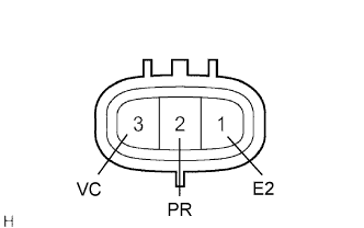 |
Disconnect the F9 sensor connector.
Measure the resistance of the sensor.
| Tester Connection | Specified Condition |
| 1 (E2) - 2 (PR) | 3 kΩ or less |
| 2 (PR) - 3 (VC) | 16.4 kΩ or less |
|
| ||||
| OK | |
| 23.CHECK WIRE HARNESS (FUEL PRESSURE SENSOR - ECM) |
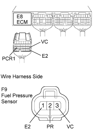 |
Disconnect the E8 ECM connector.
Disconnect the F9 sensor connector.
Measure the resistance of the wire harness side connectors.
| Tester Connection | Specified Condition |
| E8-26 (PCR1) - F9-2 (PR) | Below 1 Ω |
| E8-18 (VC) - F9-3 (VCC) | Below 1 Ω |
| E8-28 (E2) - F9-1 (E2) | Below 1 Ω |
| E8-26 (PCR1) or F9-2 (PR) - Body ground | 10 kΩ or higher |
| E8-18 (VC) or F9-3 (VC) - Body ground | 10 kΩ or higher |
| E8-28 (E2) or F9-1 (E2) - Body ground | 10 kΩ or higher |
|
| ||||
| OK | |
| 24.REPLACE ECM |
|
| ||||
| OK | ||
| ||
