ECD SYSTEM > Black Smoke Emitted |
| 1.CHECK OUTPUT DTC (RELATED TO ENGINE) |
Connect the intelligent tester to the DLC3.
Turn the ignition switch ON and turn the intelligent tester ON.
Enter the following menus: Powertrain / Engine / DTC.
Read the DTCs.
| Display (DTC Output) | Proceed to |
| No output | A |
| DTCs related to the engine (Click here) | B |
|
| ||||
| A | |
| 2.READ VALUE OF INJECTOR ASSEMBLY (INJECTION VOLUME AND INJECTION FEED BACK VAL #1 TO #4) |
Connect the intelligent tester to the DLC3.
Start the engine and turn the intelligent tester ON.
Enter the following menus: Powertrain / Engine / Data List.
Select the following menu items in order and read the values.
| Item | Engine Speed* | Reference Value |
| Injection Volume | Idling (No engine load) | 3 to 10 mm3
|
| Injection Feedback Val #1 | Idling (No engine load) | -3.0 to 3.0 mm3
|
| Injection Feedback Val #2 | Idling (No engine load) | -3.0 to 3.0 mm3
|
| Injection Feedback Val #3 | Idling (No engine load) | -3.0 to 3.0 mm3
|
| Injection Feedback Val #4 | Idling (No engine load) | -3.0 to 3.0 mm3
|
|
| ||||
| OK | |
| 3.PERFORM ENGINE RPM ACCELERATION |
Accelerate the engine speed to the maximum rpm with no load 20 times.
Check the volume of black smoke in the exhaust gas.
| Result | Proceed to |
| Black smoke is not present | OK |
| Black smoke remains in the exhaust gas | NG |
|
| ||||
| NG | |
| 4.CHECK AIR INTAKE SYSTEM AND EXHAUST SYSTEM |
Remove the air cleaner filter.
Inspect the throttle valve operation.
Start the engine.
Check if the throttle valve fully opens when accelerating the engine speed.
|
| ||||
| OK | |
| 5.CHECK TURBOCHARGING PRESSURE |
Check the turbocharger pressure (Click here).
|
| ||||
| OK | |
| 6.PERFORM ACTIVE TEST BY FUEL PRESSURE SENSOR AND INJECTOR ASSEMBLY |
Connect the intelligent tester to the DLC3.
Start the engine and turn the intelligent tester ON.
Enter the following menus: Powertrain / Engine / Data List.
Select the following menu items in order and read the values.
| Item | Engine Speed* | Reference Value |
| Fuel Pressure | Idling | 25 to 35 MPa |
| Fuel Pressure | 2,000 rpm (no engine load) | 25 to 35 MPa |
| Fuel Pressure | 3,000 rpm (no engine load) | 35 to 45 MPa |
| Injection Volume | Idling | 3 to 10 mm3
|
| Injection Volume | 2,000 rpm (no engine load) | 3 to 10 mm3
|
| Injection Volume | 3,000 rpm (no engine load) | 4 to 12 mm3
|
| Main Injection | Idling | 525 to 675 μs |
| Pilot 2 Injection | Idling | 350 to 450 μs |
| Injection Feedback Val #1 | Idling | -3.0 to 3.0 mm3
|
| Injection Feedback Val #2 | Idling | -3.0 to 3.0 mm3
|
| Injection Feedback Val #3 | Idling | -3.0 to 3.0 mm3
|
| Injection Feedback Val #4 | Idling | -3.0 to 3.0 mm3
|
| Result | Proceed to |
| Within reference value | A |
| One of Injection Feedback Val #1 to #4 is not within reference value | B |
| Other result | C |
|
| ||||
|
| ||||
| A | |
| 7.INSPECT CYLINDER COMPRESSION PRESSURE |
Check the cylinder compression pressure (Click here).
|
| ||||
| OK | |
| 8.CHECK HARNESS AND CONNECTOR (INJECTOR ASSEMBLY - EDU) |
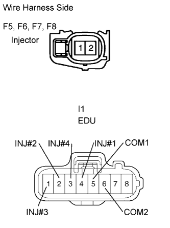 |
Disconnect the F5, F6, F7 and F8 injector connectors.
Disconnect the I1 EDU connector.
Measure the resistance of the wire harness side connectors.
| Tester Connection | Specified Condition |
| F5-1 - I1-4 (INJ#1) | Below 1 Ω |
| F6-1 - I1-2 (INJ#2) | Below 1 Ω |
| F7-1 - I1-1 (INJ#3) | Below 1 Ω |
| F8-1 - I1-3 (INJ#4) | Below 1 Ω |
| F5-2 - I1-5 (COM1) | Below 1 Ω |
| F6-2 - I1-6 (COM2) | Below 1 Ω |
| F7-2 - I1-6 (COM2) | Below 1 Ω |
| F8-2 - I1-5 (COM1) | Below 1 Ω |
| F5-1 or I1-4 (INJ#1) - Body ground | 10 kΩ or higher |
| F6-1 or I1-2 (INJ#2) - Body ground | 10 kΩ or higher |
| F7-1 or I1-1 (INJ#3) - Body ground | 10 kΩ or higher |
| F8-1 or I1-3 (INJ#4) - Body ground | 10 kΩ or higher |
| F5-2 or I1-5 (COM1) - Body ground | 10 kΩ or higher |
| F6-2 or I1-6 (COM2) - Body ground | 10 kΩ or higher |
| F7-2 or I1-6 (COM2) - Body ground | 10 kΩ or higher |
| F8-2 or I1-5 (COM1) - Body ground | 10 kΩ or higher |
|
| ||||
| OK | |
| 9.PERFORM ACTIVE TEST BY INTELLIGENT TESTER (CONTROL THE CYLINDER FUEL CUT) |
Connect the intelligent tester to the DLC3.
Start the engine and turn the intelligent tester ON.
Enter the following menus: Powertrain / Engine / Active Test / Control the Cylinder#1, #2, #3 and #4 Fuel Cut.
Check the engine idling condition while the fuel injection of each cylinder is cut using the intelligent tester.
| Engine Idling Condition | Proceed To |
| Becomes unstable | A |
| Does not change | B |
|
| ||||
| A | ||
| ||
| 10.CHECK AND REPLACE ECM TERMINAL VOLTAGE (THW TERMINAL) |
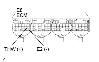 |
Start the engine.
Measure the voltage of the ECM connector.
| Tester Connection | Condition | Specified Condition |
| E8-19 (THW) - E8-28 (E2) | Idling, engine coolant temperature between 60 and 120°C (140 and 248°F) | 0.2 to 1.0 V |
|
| ||||
| OK | |
| 11.CHECK ECM TERMINAL VOLTAGE (PIM TERMINAL) |
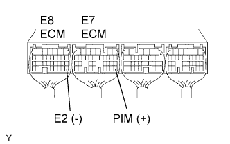 |
Turn the ignition switch ON.
Measure the voltage of the ECM connectors.
| Tester Connection | Condition | Specified Condition |
| E7-28 (PIM) - E8-28 (E2) | Applied negative pressure of 40 kPa (300 mmHg, 11.8 in.Hg) | 1.3 to 1.9 V |
| E7-28 (PIM) - E8-28 (E2) | Same as atmospheric pressure | 2.4 to 3.1 V |
| E7-28 (PIM) - E8-28 (E2) | Applied positive pressure of 69 kPa (518 mmHg, 20.4 in.Hg) | 2.7 to 4.3 V |
|
| ||||
| OK | |
| 12.CHECK ECM TERMINAL VOLTAGE (NE+ AND NE- TERMINALS) |
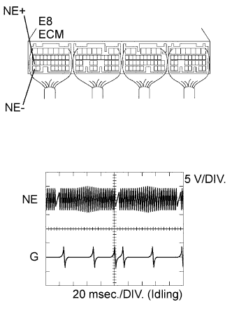 |
While idling the engine, check the waveform of the ECM connector using an oscilloscope.
| Tester Connection | Specified Condition |
| E8-27 (NE+) - E8-34 (NE-) | Correct waveform is shown |
| Tool Setting | Condition |
| 5 V/DIV., 20 msec./DIV. | Idling with warm engine |
|
| ||||
| OK | |
| 13.CHECK ECM TERMINAL VOLTAGE (VPA AND VPA2 TERMINALS) |
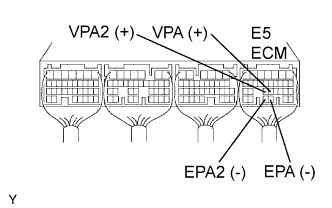 |
Turn the ignition switch ON.
Measure the voltage of the ECM connector.
| Tester Condition | Accelerator Pedal Condition | Specified Condition |
| E5-22 (VPA) - E5-28 (EPA) | Released | 0.6 to 1.0 V |
| E5-22 (VPA) - E5-28 (EPA) | Depressed | 2.9 to 4.2 V |
| E5-23 (VPA2) - E5-29 (EPA2) | Released | 1.4 to 1.8 V |
| E5-23 (VPA2) - E5-29 (EPA2) | Depressed | 3.7 to 5.0 V |
|
| ||||
| OK | |
| 14.CHECK ECM TERMINAL VOLTAGE (THA TERMINAL) |
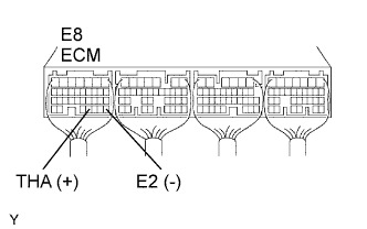 |
Start the engine.
Measure the voltage of the ECM connector.
| Tester Connection | Condition | Specified Condition |
| E8-31 (THA) - E8-28 (E2) | Idling, intake air temperature at 20°C (68°F) | 0.5 to 3.4 V |
|
| ||||
| OK | |
| 15.CHECK ECM TERMINAL VOLTAGE (PCR1 TERMINAL) |
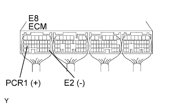 |
Start the engine.
Measure the voltage of the ECM connector.
| Tester Connection | Condition | Specified Condition |
| E8-26 (PCR1) - E8-28 (E2) | Idling | 1.3 to 1.8 V |
|
| ||||
| OK | ||
| ||
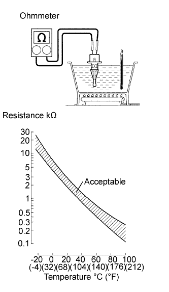
| 16.INSPECT ENGINE COOLANT TEMPERATURE SENSOR |
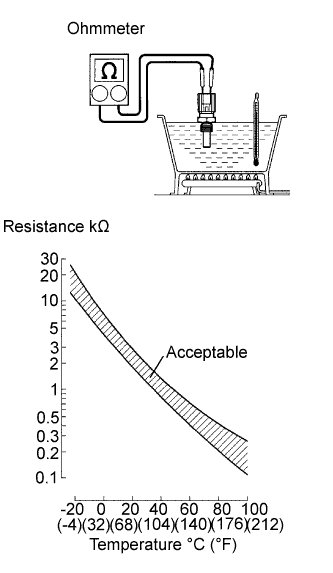 |
Remove the sensor.
Measure the resistance of the sensor.
| Connection | Specified Condition |
| 20°C (68°F) | 2.32 to 2.59 kΩ |
| 80°C (176°F) | 0.310 to 0.326 kΩ |
|
| ||||
| OK | ||
| ||
| 17.CHECK HARNESS AND CONNECTOR (MANIFOLD ABSOLUTE PRESSURE SENSOR - ECM) |
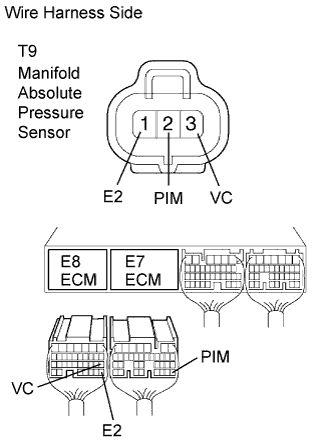 |
Disconnect the T9 sensor connector.
Disconnect the E7 and E8 ECM connectors.
Measure the resistance of the wire harness side connectors.
| Tester Connection | Specified Condition |
| T9-2 (PIM) - E7-28 (PIM) | Below 1 Ω |
| T9-3 (VC) - E8-18 (VC) | Below 1 Ω |
| T9-1 (E2) - E8-28 (E2) | Below 1 Ω |
| T9-2 (PIM) or E7-28 (PIM) - Body ground | 10 kΩ or higher |
| T9-3 (VC) or E8-18 (VC) - Body ground | 10 kΩ or higher |
| T9-1 (E2) or E8-28 (E2) - Body ground | 10 kΩ or higher |
|
| ||||
| OK | ||
| ||
| 18.INSPECT CRANKSHAFT POSITION SENSOR |
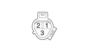 |
Disconnect the C4 sensor connector.
Measure the resistance of the sensor.
| Tester Connection | Condition | Specified Condition |
| 1 - 2 | Cold | 1,630 to 2,740 Ω |
| 1 - 2 | Hot | 2,065 to 3,225 Ω |
|
| ||||
| OK | ||
| ||
| 19.CHECK HARNESS AND CONNECTOR (ACCELERATOR PEDAL POSITION SENSOR - ECM) |
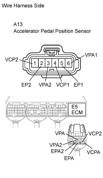 |
Disconnect the A13 sensor connector.
Disconnect the E5 ECM connector.
Measure the resistance of the wire harness side connectors.
| Tester Connection | Specified Condition |
| A13-1 (VCP2) - E5-27 (VCP2) A13-2 (EPA2) - E5-29 (EPA2) A13-3 (VPA2) - E5-23 (VPA2) A13-4 (VCP1) - E5-20 (VCPA) A13-5 (EP1) - E5-28 (EPA) A13-6 (VPA1) - E5-22 (VPA) | Below 1 Ω |
| A13-1 (VCP2) or E5-27 (VCP2) - Body ground A13-2 (EPA2) or E5-29 (EP2) - Body ground A13-3 (VPA2) or E5-23 (VPA2) - Body ground A13-4 (VCP1) or E5-26 (VCPA) - Body ground A13-5 (EP1) or E5-28 (EPA) - Body ground A13-6 (VPA1) or E5-22 (VPA) - Body ground | 10 kΩ or higher |
|
| ||||
| OK | ||
| ||
| 20.INSPECT INTAKE AIR TEMPERATURE SENSOR |
 |
Remove the sensor.
Measure the resistance of the sensor.
| Tester Connection | Condition | Specified Condition |
| 1 - 2 | 20°C (68°F) | 2.21 to 2.69 kΩ |
|
| ||||
| OK | ||
| ||
| 21.INSPECT COMMON RAIL ASSEMBLY (FUEL PRESSURE SENSOR) |
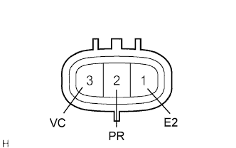 |
Disconnect the F9 sensor connector.
Measure the resistance of the sensor.
| Tester Connection | Specified Condition |
| 1 (E2) - 2 (PR) | 3 kΩ or less |
| 2 (PR) - 3 (VC) | 16.4 kΩ or less |
|
| ||||
| OK | |
| 22.CHECK HARNESS AND CONNECTOR (FUEL PRESSURE SENSOR - ECM) |
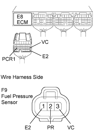 |
Disconnect the E8 ECM connector.
Disconnect the F9 sensor connector.
Measure the resistance of the wire harness side connectors.
| Tester Connection | Specified Condition |
| E8-26 (PCR1) - F9-2 (PR) | Below 1 Ω |
| E8-18 (VC) - F9-3 (VCC) | Below 1 Ω |
| E8-28 (E2) - F9-1 (E2) | Below 1 Ω |
| E8-26 (PCR1) or F9-2 (PR) - Body ground | 10 kΩ or higher |
| E8-18 (VC) or F9-3 (VC) - Body ground | 10 kΩ or higher |
| E8-28 (E2) or F9-1 (E2) - Body ground | 10 kΩ or higher |
|
| ||||
| OK | |
| 23.REPLACE ECM |
|
| ||||
| OK | ||
| ||
