ECD SYSTEM > Starter Signal Circuit |
| 1.READ VALUE OF STARTER SIGNAL |
Connect the intelligent tester to the DLC3.
Turn the ignition switch ON and turn the intelligent tester ON.
Enter the following menus: Powertrain / Engine / Data List / Starter Signal.
Read the values.
| Ignition Switch Position | Starter SIG |
| ON | OFF |
| START | ON |
|
| ||||
| NG | |
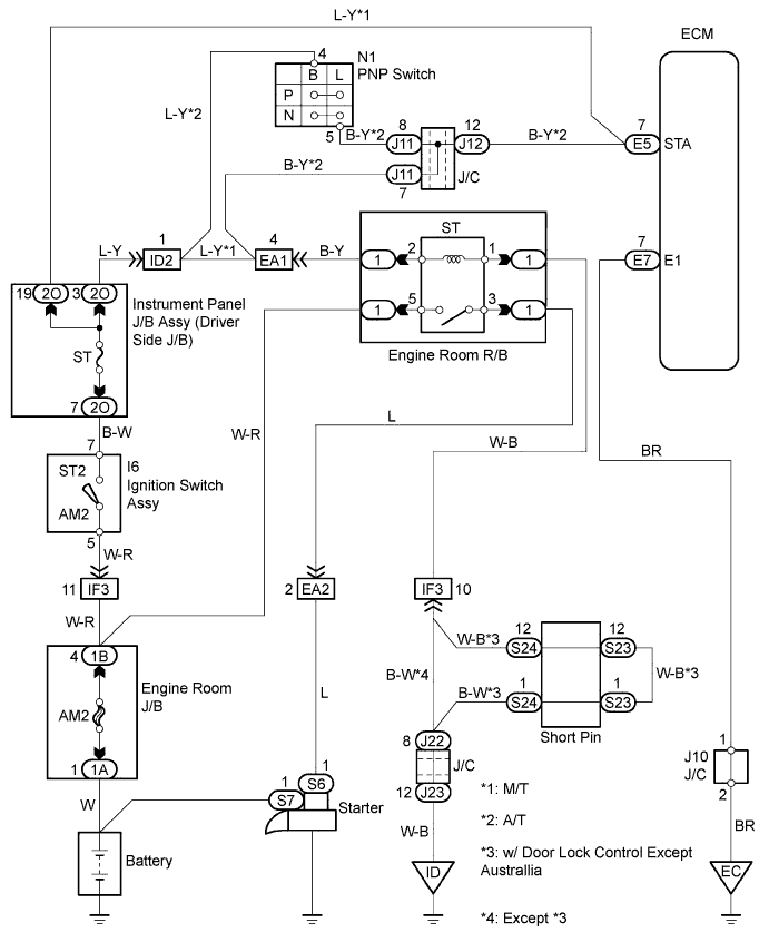
| 2.CHECK WIRE HARNESS (ECM - ST RELAY) |
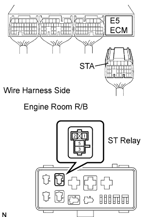 |
Disconnect the E5 ECM connector.
A/T:
Remove the ST relay from the engine room J/B.
M/T:
Disconnect the 2O J/B connector.
Measure the resistance of the wire harness side connectors.
| Tester Connection | Specified Condition |
| R/B ST relay terminal 2 - E5-7 (STA) | Below 1 Ω |
| R/B ST relay terminal 2 or E5-7 (STA) - Body ground | 10 kΩ or higher |
| Tester Connection | Specified Condition |
| 2O-19 - E5-7 (STA) | Below 1 Ω |
| 2O-19 - E5-7 (STA) - Body ground | 10 kΩ or higher |
|
| ||||
| OK | ||
| ||
