DTC    P0136    Oxygen Sensor Circuit Malfunction (Bank 1 Sensor 2)

DTC    P0137    Oxygen Sensor Circuit Low Voltage (Bank 1 Sensor 2)

DTC    P0138    Oxygen Sensor Circuit High Voltage (Bank 1 Sensor 2)

DTC    P0156    Oxygen Sensor Circuit Malfunction (Bank 2 Sensor 2)

DTC    P0157    Oxygen Sensor Circuit Low Voltage (Bank 2 Sensor 2)

DTC    P0158    Oxygen Sensor Circuit High Voltage (Bank 2 Sensor 2)

for Preparation Click here


DESCRIPTION

The heated oxygen sensor is a planar type. Compared to the conventional type, the sensor and heater portions are narrower. The heat of the heater is conducted to the zirconia element through the alumina, accelerating sensor activation.
To obtain a high purification rate of carbon monoxide (CO), hydrocarbon (HC) and nitrogen oxide (NOx) in the exhaust gas, a Three-Way Catalytic Converter (TWC) is used. For the most efficient use of the three-way catalytic converter, the air-fuel ratio must be precisely controlled so that it is always close to the stoichiometric air-fuel ratio.
The heated oxygen sensor has the characteristic whereby its output voltage changes suddenly in the vicinity of the stoichiometric air-fuel ratio. This is used to detect the oxygen concentration in the exhaust gas and provide the ECM with feedback control the air-fuel ratio.
When the air-fuel ratio becomes lean, the oxygen concentration in the exhaust gas increases. And the heated oxygen sensor informs the ECM of the lean condition (small electromotive force: Less than 0.45 V).
When the air-fuel ratio is richer than the stoichiometric air-fuel ratio, the oxygen concentration in the exhaust gas is reduced. And the heated oxygen sensor informs the ECM of the rich condition (large electromotive force: More than 0.45 V). The ECM judges by the electromotive force from the heated oxygen sensor whether the air-fuel ratio is rich or lean and controls the injection time accordingly. If the malfunction of the heated oxygen sensor causes an output of abnormal electromotive force, the ECM becomes unable to perform the accurate air-fuel ratio control.
The heated oxygen sensors include a heater which heats the zirconia element. The heater is controlled by the ECM. When the intake air volume is low (the temperature of the exhaust gas is low), current flows to the heater in order to heat the sensor for accurate oxygen concentration detection.

A090870E01


DTC No.
DTC Detection Condition
Trouble Area
P0136
P0156
During active control, heated oxygen sensor output voltage is 0.2 to 0.6 V
  1. Open or short in heated oxygen sensor (bank 1, 2 sensor 2) circuit
  2. Heated oxygen sensor (bank 1, 2 sensor 2)
  3. Heated oxygen sensor heater (bank 1, 2 sensor 2)
  4. Integration relay
P0136
P0156
(a) and (b) are met for more than 90 seconds
(a) Estimated rear oxygen sensor temperature is less than 800°C (1,472°F)
(b) Rear oxygen sensor impedance is less than 5 Ω
P0137
P0157
During active control, heated oxygen sensor output voltage is less than 0.2 V
P0137
P0157
(a) and (b) are met for more than 90 seconds
(a) Estimated rear oxygen sensor temperature is less than 450°C (842°F)
(b) Rear oxygen sensor impedance is more than 15 kΩ
P0138
P0158
During active control, heated oxygen sensor output voltage is more than 0.6 V
P0138
P0158
Rear oxygen sensor output voltage is 1.2 V or higher for more than 30 seconds

HINT:
  1. Bank 1 refers to the bank that includes the No. 1 cylinder.
  2. Bank 2 refers to the bank that does not include the No. 1 cylinder.
  3. Sensor 2 refers to the sensor farther away from the engine assembly.


WIRING DIAGRAM


A112671E01


CONFIRMATION DRIVING PATTERN

HINT:
Performing this confirmation pattern will activate the DTC detection (P0136) of the ECM. This is very useful for verifying the completion of a repair.


A092806E03

  1. (a) Clear the DTC (Click here).
  2. (b) Using the tester, change the ECM from normal mode to check mode (Click here).
  3. (c) Start the engine and warm it up with all the accessory switches OFF.
  4. (d) Deactivate the inspection mode and drive the vehicle at 70 to 120 km/h (44 to 70 mph) for 5 to 10 minutes.
  5. (e) Read DTCs.

NOTICE:
If the conditions in this test are not strictly followed, no malfunction will be detected.


INSPECTION PROCEDURE

  1. (a) Connect the intelligent tester to the DLC3.

HINT:
It is possible the malfunctioning area can be found using the Active Test "Control the injection volume for A/F sensor" operation. The Active Test can determine if the heated oxygen sensor or other potential trouble areas are malfunctioning or not.
The injection volume can be switched to -12.5% (decrease) or +25% (increase) by the Active Test.
The Active Test procedure enables a technician to check and graph the output voltage of the heated oxygen sensors.

  1. (b) Turn the ignition switch ON.
  1. (c) Warm up the engine with the engine speed at 2,500 rpm for approximately 90 seconds.
  1. (d) Enter the following menus: Powertrain / Engine and ECT / Active Test / Control the injection volume for A/F sensor.
  1. (e) Perform the Active Test while the engine is idling.

Standard voltage:

Tester Display
(Sensor)
Injection Volume
Status
Voltage
AFS B1S1 or AFS B2S1
(A/F)
+25%
Rich
Less than 3.0 V
AFS B1S1 or AFS B2S1
(A/F)
-12.5%
Lean
More than 3.35 V
O2S B1S1 or O2S B2S2
(heated oxygen sensor)
+25%
Rich
More than 0.55 V
O2S B1S1 or O2S B2S2
(heated oxygen sensor)
-12.5%
Lean
Less than 0.4 V

NOTICE:
The A/F sensor output has a few seconds of delay and the heated oxygen sensor output has approximately 20 seconds of delay.


Case
Output Voltage of A/F Sensor
(Sensor 1)
Output Voltage of Heated Oxygen Sensor
(Sensor 2)
Mainly Suspected Trouble Area
1
Injection volume
+25%
-12.5%
A103184
Injection volume
+25%
-12.5%
A103184
-
Output voltage
More than 3.35 V
Less than 3.0 V
A103187
Output voltage
More than 0.55 V
Less than 0.4 V
A103186
2
Injection volume
+25%
-12.5%
A103184
Injection volume
+25%
-12.5%
A103184
A/F sensor
(A/F sensor, heater, A/F sensor circuit)
Output voltage
Almost no reaction
A103185
Output voltage
More than 0.55 V
Less than 0.4 V
A103186
3
Injection volume
+25%
-12.5%
A103184
Injection volume
+25%
-12.5%
A103184
Heated oxygen sensor
(heated oxygen sensor, heater, heated oxygen sensor circuit)
Output voltage
More than 3.35 V
Less than 3.0 V
A103187
Output voltage
Almost no reaction
A103185
4
Injection volume
+25%
-12.5%
A103184
Injection volume
+25%
-12.5%
A103184
Extremely rich or lean actual air-fuel ratio
(injector, fuel pressure, gas leakage in exhaust system, etc. )
Output voltage
Almost no reaction
A103185
Output voltage
Almost no reaction
A103185
The following "Control the injection volume for A/F sensor" procedure enables the technician to check and graph the output voltage of both A/F sensor and heated oxygen sensor.

HINT:
  1. Read freeze frame data using the intelligent tester. Freeze frame data records the engine conditions when a malfunction is detected. When troubleshooting, freeze frame data can help determine if the vehicle was running or stopped, if the engine was warmed up or not, if the air-fuel ratio was lean or rich, and other data from the time the malfunction occurred.
  2. A low A/F sensor voltage could be caused by a rich air-fuel mixture. Check the conditions that would cause the engine to run with a rich air-fuel mixture.
  3. A high A/F sensor voltage could be caused by a lean air-fuel mixture. Check the conditions that would cause the engine to run with a lean air-fuel mixture.
  4. Sensor 2 refers to the sensor mounted behind the Three-Way Catalytic Converter (TWC) and located far from the engine assembly.

1.CHECK OTHER DTC OUTPUT (BESIDES DTC P0136, P0137, P0138, P0156, P0157 AND/OR P0158)
  1. Connect the intelligent tester to the DLC3.

  1. Turn the ignition switch ON and turn the tester ON.

  1. Enter the following menus: Powertrain / Engine and ECT / DTC.

  1. Read the DTCs.

    Result:
    Display (DTC output)
    Proceed to
    Only P0136, P0137, P0138, P0156, P0157 and/or P0158 are output
    A
    P0136, P0137, P0138, P0156, P0157 and/or P0158 and other DTCs are output
    B

    HINT:
    If any other codes besides P0136, P0137, P0138, P0156, P0157 and/or P0158 are output, perform troubleshooting for those DTCs first.


B
GO TO RELEVANT DTC CHART
A


2.READ DATA LIST (OUTPUT VOLTAGE OF HEATED OXYGEN SENSOR)
  1. After warming up the engine, race the engine at 2,500 rpm for 3 minutes.

  1. Read the output voltage of the heated oxygen sensor when the engine is suddenly raced.

    HINT:
    Quickly perform racing to 4,000 rpm 3 times by using the accelerator pedal.

    Standard voltage:
    Alternates between 0.4 V or less and 0.5 V or more.


OK
Go to step 6
NG


3.INSPECT HEATED OXYGEN SENSOR (HEATER RESISTANCE)
A113537E01
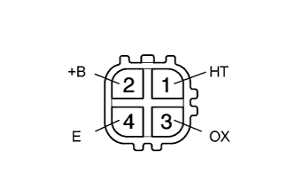
  1. Disconnect the sensor connector.

  1. Measure the resistance of the sensor.

    Standard resistance:
    Tester Connection
    Specified Condition
    1 (HT) - 2 (+B)
    10 to 17 Ω at 20°C (68°F)
    1 (HT) - 4 (E)
    10 kΩ or higher


NG
REPLACE HEATED OXYGEN SENSOR
OK


4.INSPECT INTEGRATION RELAY (MAIN RELAY)
G034717E04
  1. Disconnect the integration relay from the engine room junction block.

  1. Measure the voltage of the MAIN relay.

    Standard resistance:
    Tester Connection
    Condition
    Specified Condition
    1J-5 - Body ground
    Ignition switch ON
    10 to 14 V


NG
REPLACE INTEGRATION RELAY
OK


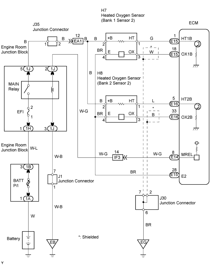
5.CHECK WIRE HARNESS (HEATED OXYGEN SENSOR - ECM)
A112672E01

A112438E01

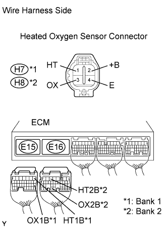
  1. Disconnect the H7 or H8 connector.

  1. Disconnect the E15 or E16 ECM connector.

  1. Measure the resistance of the wire harness side connectors.

    Standard resistance:
    Tester Connection
    Specified Condition
    H7-1 (HT) - E15-1 (HT1B)
    Below 1 Ω
    H7-3 (OX) - E15-18 (OX1B)
    Below 1 Ω
    H8-1 (HT) - E16-5 (HT2B)
    Below 1 Ω
    H8-3 (OX) - E16-33 (OX2B)
    Below 1 Ω
    H7-1 (HT) or E15-1 (HT1B) - Body ground
    10 kΩ or higher
    H7-3 (OX) or E15-18 (OX1B) - Body ground
    10 kΩ or higher
    H8-1 (HT) or E16-5 (HT2B) - Body ground
    10 kΩ or higher
    H8-3 (OX) or E16-33 (OX2B) - Body ground
    10 kΩ or higher


NG
REPAIR OR REPLACE HARNESS AND CONNECTOR
OK

REPLACE HEATED OXYGEN SENSOR 

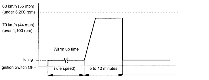
6.PERFORM CONFIRMATION DRIVING PATTERN

HINT:
Clear all DTCs prior to performing the confirmation driving pattern.


GO


7.READ OUTPUT DTC (DTC P0136 AND/OR P0156 ARE OUTPUT AGAIN)
  1. Connect the intelligent tester to the DLC3.

  1. Turn the ignition switch ON and turn the tester ON.

  1. Enter the following menus: Powertrain / Engine and ECT / DTC.

  1. Read the DTCs.

    Result:
    Display (DTC output)
    Proceed to
    P0136 and/or P0156 are not output again
    A
    P0136 and/or P0156 are output again
    B


B
REPLACE HEATED OXYGEN SENSOR
A

CHECK FOR INTERMITTENT PROBLEMS