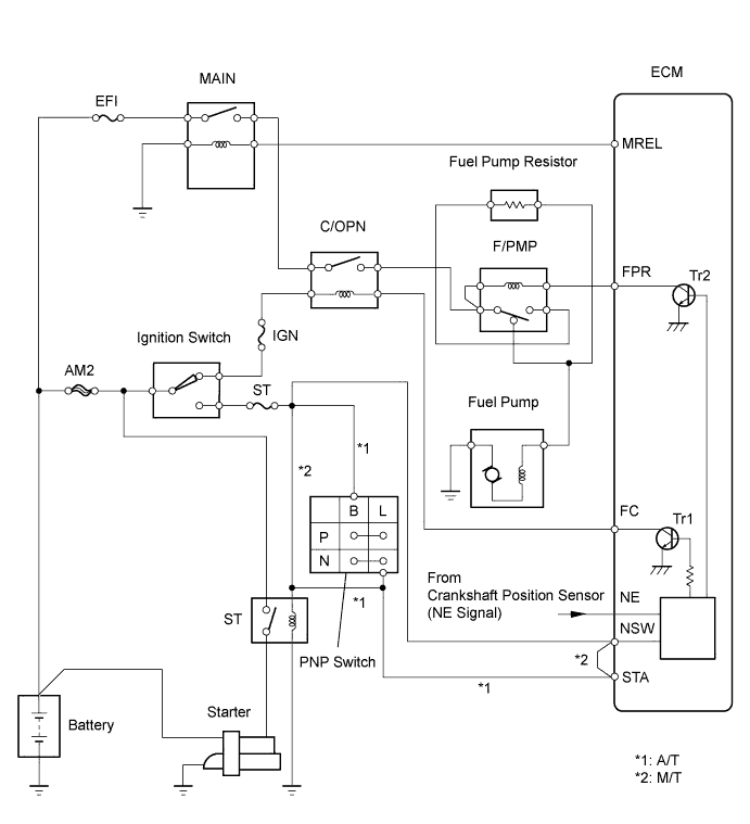
DTC P0230 Fuel Pump Primary Circuit |
| DTC No. | DTC Detection Condition | Trouble Area |
| P0230 | Open or short in F/PMP relay circuit for 0.5 second or more (1 trip detection logic) |
|
| 1.INSPECT ECM (FPR VOLTAGE) |
 |
Measure the voltage of the ECM connectors.
| Tester Connection | Condition | Specified Condition |
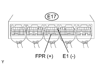
| E17-30 (FPR) - E17-1 (E1) | STA signal ON | 9 to 14 V |
| E17-30 (FPR) - E17-1 (E1) | STA signal OFF | 0 to 3 V |
|
| ||||
| OK | |
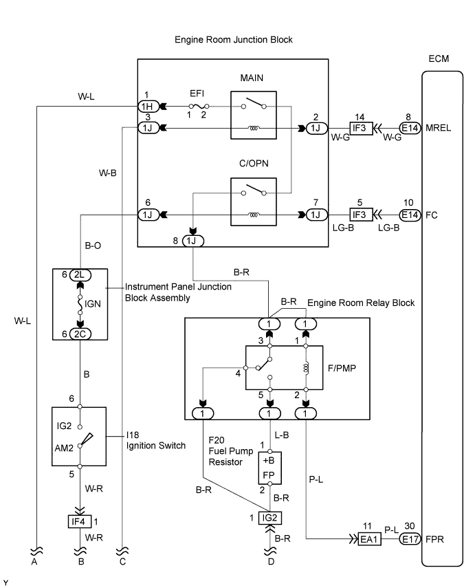
| 2.INSPECT RELAY (Marking: F/PMP) |
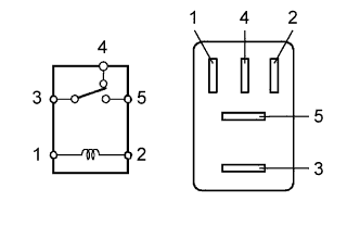 |
Remove the F/PMP relay from the engine room relay block.
Measure the resistance the relay.
| Tester Connection | Specified Condition |
| 3 - 4 | Below 1 Ω |
| 3 - 5 | 10 kΩ or higher |
| 3 - 4 | 10 kΩ or higher (when battery voltage applied to terminals 1 and 2) |
| 3 - 5 | Below 1 Ω (when battery voltage applied to terminals 1 and 2) |
|
| ||||
| OK | |
| 3.CHECK WIRE HARNESS (F/PMP RELAY - ECM) |
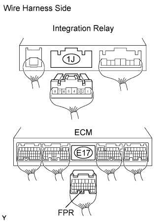 |
Remove the F/PMP relay from the engine room relay block.
Disconnect the E17 ECM connector.
Measure the resistance of the wire harness side connectors.
| Tester Connection | Specified Condition |
| F/PMP relay (2) - E17-30 (FPR) | Below 1 Ω |
| F/PMP relay (2) or E17-30 (FPR) - Body ground | 10 kΩ or higher |
|
| ||||
| OK | ||
| ||
