LOWER INSTRUMENT PANEL > INSTALLATION |
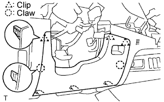
| 1. INSTALL INSTRUMENT PANEL SUB-ASSEMBLY LOWER |
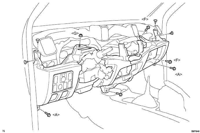
Install the hood lock control cable lever and fuel lid control cable lever.
Connect all connectors, and attach all clamps to install the panel.
Install the panel with the 3 screws <F>, 2 bolts <A> and nut <G>.
| 2. INSTALL COWL SIDE TRIM BOARD LH |
Install the cowl side trim board LH (Click here or Click here or Click here).
| 3. INSTALL COWL SIDE TRIM BOARD RH |
Install the cowl side trim board RH (Click here or Click here or Click here).
| 4. INSTALL FRONT DOOR SCUFF PLATE LH |
Install the front door scuff plate LH (Click here or Click here or Click here).
| 5. INSTALL FRONT DOOR SCUFF PLATE RH |
Install the front door scuff plate RH (Click here or Click here or Click here).
| 6. INSTALL SWITCH BASE |
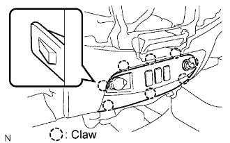 |
Connect all connectors.
Attach the 8 claws to install the switch base.
| 7. INSTALL NO. 1 INSTRUMENT PANEL BOX |
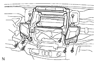 |
Connect all connectors.
Attach all clamps to install the panel box.
Install the panel box with the 6 screws <B> and 2 clips.
| 8. INSTALL CONSOLE BOX ASSEMBLY |
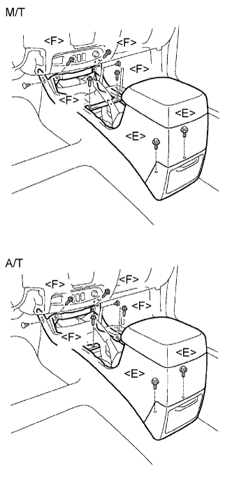 |
Install the console box with the 2 clips, 4 screws <F> and 2 bolts <E>.
| 9. INSTALL CONSOLE PANEL SUB-ASSEMBLY UPPER |
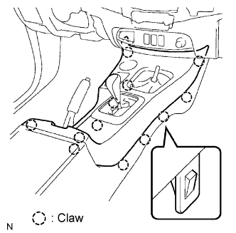 |
Attach the 12 claws to install the console panel.
| 10. INSTALL PARKING BRAKE HOLE COVER SUB-ASSEMBLY |
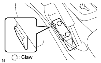 |
Attach the 4 claws to install the hole cover.
| 11. INSTALL SHIFT LEVER KNOB SUB-ASSEMBLY |
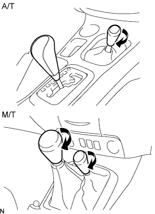 |
w/ M/T:
Twist the knob in the direction indicated by the arrow to install it.
w/ 4WD:
Twist the transfer shift lever knob in the direction indicated by the arrow to install it.
| 12. INSTALL INSTRUMENT PANEL FINISH PANEL SUB-ASSEMBLY LOWER |
 |
Attach the 2 claws and 3 clips to install the panel.
| 13. INSTALL HEADLIGHT DIMMER SWITCH ASSEMBLY |
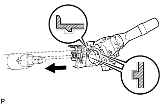 |
Install the headlight dimmer switch with the claw as shown in the illustration.
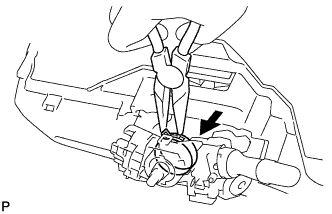 |
Install the headlight dimmer switch with the clamp.
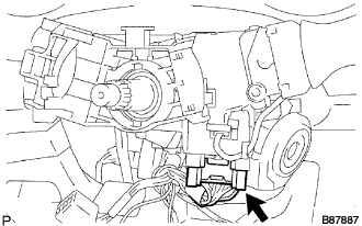 |
Connect the connector.
| 14. INSTALL WINDSHIELD WIPER SWITCH ASSEMBLY |
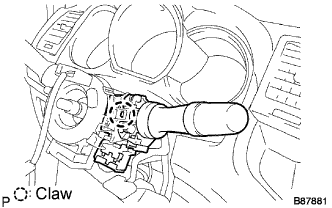 |
Attach the claw to install the wiper switch.
Connect the connectors.
| 15. INSTALL INSTRUMENT PANEL SUB-ASSEMBLY UPPER |
Install the instrument panel sub-assembly upper (Click here).
| 16. CONNECT CABLE TO NEGATIVE BATTERY TERMINAL |
| 17. PERFORM INITIALIZATION |
Perform initialization (Click here).
| 18. CHECK SRS WARNING LIGHT |
Check the SRS warning light (Click here).
