CRUISE CONTROL SYSTEM > Cruise Main Indicator Light Circuit |
| 1.PERFORM ACTIVE TEST (CRUISE MAIN INDICATOR LIGHT) |
Select the Active Test, use the intelligent tester to generate a control command, and then check that the CRUISE main indicator light illuminates.
| Item | Test Details | Diagnostic Note |
| Indicator. Light Cruise | CRUISE main indicator light is ON/OFF | - |
|
| ||||
| NG | |
| 2.INSPECT FUSE (MET) |
Remove the MET fuse from the instrument panel junction block.
Measure the resistance of the fuse.
|
| ||||
| OK | |
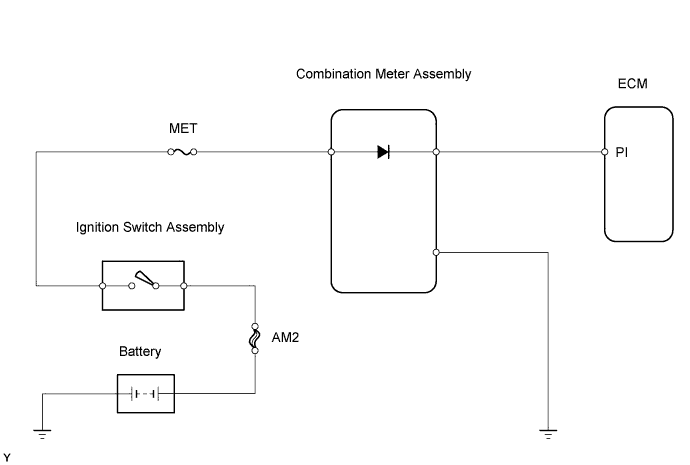
| 3.CHECK WIRE HARNESS (COMBINATION METER ASSEMBLY - ECM, BATTERY AND BODY GROUND) |
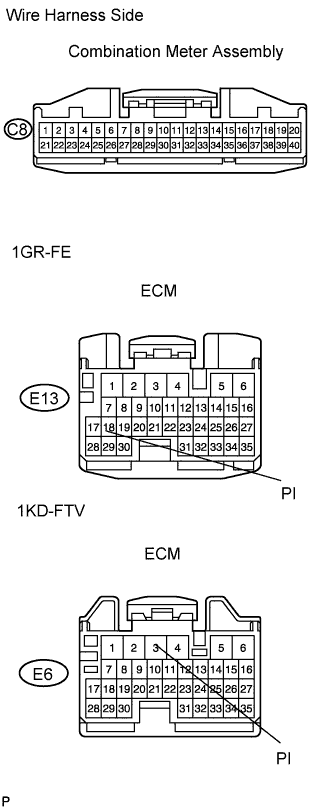 |
Disconnect the E13 or E6 ECM connector.
Disconnect the C8 meter connector.
Measure the voltage and resistance of the wire harness side connectors.
| Tester Connection | Switch Condition | Specified Condition |
| C8-21 - Body ground | Ignition switch ON | 10 to 14 V |
| C8-21 - Body ground | Ignition switch OFF | Below 1 V |
| Tester Connection | Switch Condition | Specified Condition |
| C8-28 - E13-18(PI) | Always | Below 1 Ω |
| C8-28 - Body ground | Always | 10 kΩ or higher |
| C8-22 - Body ground | Always | Below 1 Ω |
| Tester Connection | Switch Condition | Specified Condition |
| C8-28 - E6-3(PI) | Always | Below 1 Ω |
| C8-28 - Body ground | Always | 10 kΩ or higher |
| C8-22 - Body ground | Always | Below 1 Ω |
|
| ||||
| OK | ||
| ||
