CRUISE CONTROL SYSTEM > TERMINALS OF ECU |
| CHECK ECM (1GR-FE) |
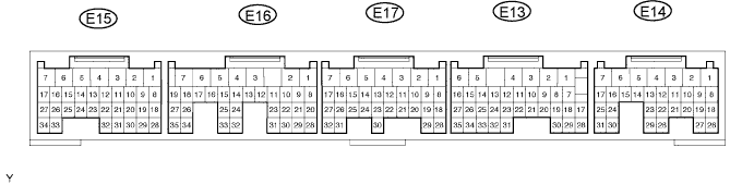
Disconnect the E14, E15 and E17 ECM connectors.
Measure the voltage and resistance of the wire harness side connectors.
| Symbols (Terminal No.) | Wiring Color | Terminal Description | Condition | Specified Condition |
| BATT (E14-3) - E1 (E17-1) | L - BR | Battery | Always | 10 to 14 V |
| IGSW (E14-9) - E1 (E17-1) | B-O - BR | IG power supply | Ignition switch ON | 10 to 14 V |
| IGSW (E14-9) - E1 (E17-1) | B-O - BR | IG power supply | Ignition switch OFF | Below 1 V |
| E1 (E17-1) - Body ground | BR - Body ground | Ground | Always | Below 1 Ω |
| E2 (E15-28) - Body ground | BR - Body ground | Ground | Always | Below 1 Ω |
Reconnect the E14, E15 and E17 ECM connectors.
Measure the voltage of the connectors.
| Symbols (Terminal No.) | Wiring Color | Terminal Description | Condition | Specified Condition |
| STP (E14-15) - E1 (E17-1) | G-W - BR | Stop light switch input signal | Ignition switch ON, release brake pedal | Below 1 V |
| STP (E14-15) - E1 (E17-1) | G-W - BR | Stop light switch input signal | Ignition switch ON, depress brake pedal | 10 to 14 V |
| ST1- (E14-16) - E1 (E17-1) | R-L - BR | Cruise cancel input signal | Ignition switch ON, depress brake pedal | Below 1 V |
| ST1- (E14-16) - E1 (E17-1) | R-L - BR | Cruise cancel input signal | Ignition switch ON, release brake pedal | 10 to 14 V |
| CCS (E13-2) - E1 (E17-1) | G-W - BR | Cruise control main switch signal | Ignition switch ON | 10 to 14 V |
| CCS (E13-2) - E1 (E17-1) | G-W - BR | Cruise control main switch signal | Set and hold main switch on CANCEL | 6.6 to 10.1 V |
| CCS (E13-2) - E1 (E17-1) | G-W - BR | Cruise control main switch signal | Set and hold main switch on SET/COAST | 4.5 to 7.1 V |
| CCS (E13-2) - E1 (E17-1) | G-W - BR | Cruise control main switch signal | Set and hold main switch on RES/ACC | 2.3 to 4.0 V |
| CCS (E13-2) - E1 (E17-1) | G-W - BR | Cruise control main switch signal | Press and hold main switch ON-OFF button | Below 1 V |
| CHECK ECM (1KD-FTV) |
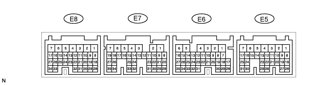
Disconnect the E5, E6, E7 and E8 ECM connectors.
Measure the voltage and resistance of the wire harness side connectors.
| Symbols (Terminal No.) | Wiring Color | Terminal Description | Condition | Specified Condition |
| BATT (E6-2) - E1 (E7-7) | L - BR | Battery | Always | 10 to 14 V |
| IGSW (E5-9) - E1 (E7-7) | B-O - BR | IG power supply | Ignition switch ON | 10 to 14 V |
| IGSW (E5-9) - E1 (E7-7) | B-O - BR | IG power supply | Ignition switch OFF | Below 1 V |
| E1 (E7-7) - Body ground | BR - Body ground | Ground | Always | Below 1 Ω |
| E2 (E8-28) - Body ground | BR - Body ground | Ground | Always | Below 1 Ω |
Reconnect the E5, E6, E7 and E8 ECM connectors.
Measure the voltage of the connectors.
| Symbols (Terminal No.) | Wiring Color | Terminal Description | Condition | Specified Condition |
| STP (E6-15) - E1 (E7-7) | G-W - BR | Stop light switch input signal | Ignition switch ON, release brake pedal | Below 1 V |
| STP (E6-15) - E1 (E7-7) | G-W - BR | Stop light switch input signal | Ignition switch ON, depress brake pedal | 10 to 14 V |
| ST1- (E6-14) - E1 (E7-7) | R-L - BR | Cruise cancel input signal | Ignition switch ON, depress brake pedal | Below 1 V |
| ST1- (E6-14) - E1 (E7-7) | R-L - BR | Cruise cancel input signal | Ignition switch ON, release brake pedal | 10 to 14 V |
| CCS (E5-21) - E1 (E7-7) | G-W - BR | Cruise control main switch signal | Ignition switch ON | 10 to 14 V |
| CCS (E5-21) - E1 (E7-7) | G-W - BR | Cruise control main switch signal | Set and hold main switch on CANCEL | 6.6 to 10.1 V |
| CCS (E5-21) - E1 (E7-7) | G-W - BR | Cruise control main switch signal | Set and hold main switch on SET/COAST | 4.5 to 7.1 V |
| CCS (E5-21) - E1 (E7-7) | G-W - BR | Cruise control main switch signal | Set and hold main switch on RES/ACC | 2.3 to 4.0 V |
| CCS (E5-21) - E1 (E7-7) | G-W - BR | Cruise control main switch signal | Press and hold main switch ON-OFF button | Below 1 V |
