SFI SYSTEM > DATA LIST / ACTIVE TEST |
| READ DATA LIST |
Warm up the engine.
Turn the ignition switch OFF.
Connect the intelligent tester to the DLC3.
Turn the ignition switch ON.
Turn the tester ON.
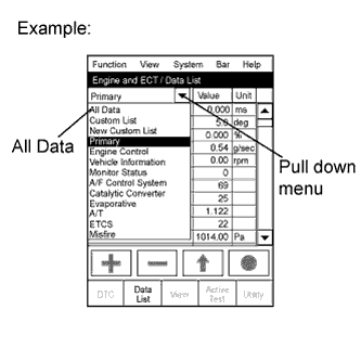 |
Enter the following menus: Powertrain / Engine and ECT / Data List.
Read the Data List on the tester's screen.
| Intelligent Tester Display | Measurement Item: Display (Range) | Normal Condition *1 | Diagnostic Note |
| Injector | Injection period of No. 1 cylinder: Min.: 0 ms, Max.: 32.64 ms | 1.3 to 2.8 ms: Idling | - |
| IGN Advance | Ignition timing advance for No. 1 cylinder: Min.: -64°, Max.: 63.5° | BTDC 7 to 24°: Idling (A/C OFF, shift position N) | - |
| Calculated Load | Calculated load by ECM: Min.: 0%, Max.: 100% | 11.4 to 16.4%: idle (A/C OFF and shift position N) 13.1 to 18.9%: 2,500 rpm (A/C OFF and shift position N) | - |
| Vehicle Load | Vehicle load: Min.: 0%, Max.: 25700% | - | - |
| MAF | Air flow rate from MAF meter: Min.: 0 g/s, Max.: 655 g/s | 3.2 to 4.7 g/s: idling 13.1 to 18.9 g/s: 2,500 rpm | If value approximately 0.0 g/s:
|
| Engine Speed | Engine speed: Min.: 0 rpm, Max.: 16,383 rpm | 650 to 750 rpm: Idle after engine warmed up | - |
| Vehicle Speed | Vehicle speed: Min.: 0 km/h, Max.: 255 km/h | Actual vehicle load | Same as speedometer indication |
| Coolant Temp | Engine coolant temperature: Min.: -40°C, Max.: 140°C | 80 to 95°C (167 to 203°F): engine warmed up |
|
| Intake Air | Intake air temperature: Min.: -40°C, Max.: 140°C | Equivalent to ambient air temperature |
|
| Air-Fuel Ratio | Air-fuel ratio: Min.: 0, Max.: 1.999 | 0.8 to 1.2: During idling | - |
| Purge Density Learn Value | Learning value of purge density: Min.: -50, Max.: 350 | - 40 to 0%: Idling | Service data |
| Purge Flow | Purge flow: Min.: 0%, Max.: 102.4% | 0 to 100%: Idling | - |
| Knock Correction Learning Value | Correction learning value of knocking: Min.: -64 crankshaft angle, Max.: 1,984 crankshaft angle | 0 to 22 crankshaft angle: Driving, 44 70 km/h (mph) | Service data |
| Knock Feedback Value | Feedback value of knocking: Min.: -64 crankshaft angle, Max.: 1,984 crankshaft angle | -22 to 0 crankshaft angle: Driving, 44 70 km/h (mph) | Service data |
| Clutch Current | Clutch current: Min.: 0 A, Max.: 2.49 A | - | - |
| Electromagnetic Clutch | Electromagnetic clutch: ON or OFF | - | - |
| Accelerator Position No. 1 | No. 1 absolute accelerator pedal position: Min.: 0%, Max.: 100% | 10 to 22%: accelerator pedal released 54 to 86%: accelerator pedal fully depressed | - |
| Accelerator Position No. 2 | No. 2 absolute accelerator pedal position: Min.: 0%, Max.: 100% | 12 to 42%: accelerator pedal released 66 to 98%: accelerator pedal fully depressed | - |
| Accelerator Position No. 1 | No. 1 absolute accelerator pedal position sensor voltage: Min.: 0 V, Max.: 4.98 V | - | ETCS freeze frame data |
| Accelerator Position No. 2 | No. 2 absolute accelerator pedal position sensor voltage: Min.: 0 V, Max.: 4.98 V | - | ETCS freeze frame data |
| Accelerator Position No. 1 | No. 1 accelerator pedal position sensor voltage: Min.: 0 V, Max.: 5 V | 0.4 to 1.4 V: Accelerator pedal released 3.1 to 4.6 V: Accelerator pedal fully depressed | - |
| Accelerator Position No. 2 | No. 2 accelerator pedal position sensor voltage: Min.: 0 V, Max.: 5 V | 1.0 to 2.2 V: Accelerator pedal released 3.9 to 5.0 V: Accelerator pedal fully depressed | - |
| Accelerator Idle Position | Whether or not accelerator pedal position sensor detecting idle: ON or OFF | ON: Idling | - |
| Throttle Fully Close Learn | No. 1 throttle valve fully closed (learned value): Min.: 0 V, Max.: 5 V | 0.4 to 0.8 V | - |
| Accel Fully Close #1 (AD) | Accelerator fully closed value (AD): Min.: 0 V, Max.: 4.98 V | - | ETCS service data |
| Accel Fully Close Learn #1 | No. 1 accelerator fully closed learning value: Min.: 0, Max.: 124.512 | - | ETCS service data |
| Accel Fully Close Learn #2 | No. 2 accelerator fully closed learning value: Min.: 0, Max.: 124.512 | - | ETCS service data |
| Fail Safe Drive | Whether or not fail-safe function executed: ON or OFF | ON: ETCS has failed | - |
| Fail Safe Drive (Main CPU) | Whether or not fail-safe function executed: ON or OFF | ON: ETCS has failed | - |
| ST1 | Brake pedal: ON or OFF | ON: Released OFF: Depressed | - |
| System Guard | System guard: ON or OFF | - | - |
| Open Side Malfunction | Open side malfunction: ON or OFF | - | ETCS service data |
| Throttle Position | Absolute throttle position sensor: Min.: 0%, Max.: 100% | 10 to 24%: throttle fully closed 64 to 96%: throttle fully open | - |
| Throttle Idle Position | Whether or not throttle position sensor detecting idle: ON or OFF | ON: Idling | - |
| Throttle Require Position | Throttle requirement position: Min.: 0 V, Max.: 5 V | 0.5 to 1.0 V: Idling | - |
| Throttle Sensor Position | Throttle sensor positioning: 0 to 100% | 0 to 10%: throttle fully closed 64 to 96%: throttle fully open | - |
| Throttle Sensor Position #2 | No. 2 absolute throttle position: 0 to 100% | 10 to 24%: throttle fully closed 64 to 96%: throttle fully open | - |
| Throttle Position No. 1 | No. 1 throttle position sensor output voltage: Min.: 0 V, Max.: 4.98 V | - | ETCS freeze frame data |
| Throttle Position No. 2 | No. 2 throttle position sensor output voltage: Min.: 0 V, Max.: 4.98 V | - | ETCS freeze frame data |
| Throttle Position No. 1 | No. 1 throttle position: Min.: 0 V, Max.: 5 V | 0.4 to 1. 4 V: Throttle fully closed 3.1 to 4.6 V: Throttle fully open | - |
| Throttle Position No. 2 | No. 2 throttle position: Min.: 0 V, Max.: 5 V | 1.0 to 2.2 V: Throttle fully closed 3.9 to 5.0 V: Throttle fully open | - |
| Throttle Position Commanded | No. 1 throttle position command value: Min.: 0 V, Max.: 4.98 V | 0.5 to 4.8 V | ETCS service data |
| Throttle Sens Open Pos #1 | Throttle sensor opener position : Min.: 0 V, Max.: 4.98 V | 0.6 to 1.0 V | ETCS service data |
| Throttle Sens Open Pos #2 | No. 2 throttle sensor opener position: Min.: 0 V, Max.: 4.98 V | 2.0 to 2.6 V | ETCS service data |
| Throttle Sens Open #1 (AD) | No. 1 Throttle sensor opener position (AD): Min.: 0 V, Max.: 4.98 V | 0.6 to 0.9 V | ETCS service data |
| Throttle Motor | Whether or not throttle motor control permitted: ON or OFF | ON: Idling | Read value with ignition switch ON (do not start engine) |
| Throttle Motor Current | Throttle actuator current: Min.: 0 A, Max.: 80 A | 0 to 3.0 A: Idling | - |
| Throttle Motor | Throttle actuator: Min.: 0%, Max.: 100% | 0.5 to 40%: Idling | - |
| Throttle Motor Current | Throttle actuator current: Min.: 0 A, Max.: 19.92 A | 0 to 3.0 A: Idling | - |
| Throttle Motor Open Duty | Throttle motor opening duty ratio: Min.: 0%, Max.: 100% | 0 to 40%: During idling | When accelerator pedal depressed, duty ratio increased |
| Throttle Motor Close Duty | Throttle actuator closed duty ratio: Min.: 0%, Max.: 100% | 0 to 40%: During idling | When accelerator pedal released quickly, duty ratio increased |
| Throttle Motor Duty (Open) | Throttle actuator duty ratio (open): Min.: 0%, Max.: 100% | - | ETCS service data |
| Throttle Motor Duty (Close) | Throttle actuator duty ratio (close): Min.: 0%, Max.: 100% | - | ETCS service data |
| O2S B1 S2 | Heated oxygen sensor output voltage for bank 1 sensor 2: Min.: 0 V, Max.: 1.275 V | 0.1 to 0.9 V: Driving 70 km/h (44 mph) | Performing Control the Injection Volume or Control the Injection Volume for A/F sensor function of Active Test enables technician to check output voltage of sensor |
| O2S B2 S2 | Heated oxygen sensor output voltage for bank 2 sensor 2: Min.: 0 V, Max.: 1.275 V | 0.1 to 0.9 V: Driving 70 km/h (44 mph) | Performing Control the Injection Volume or Control the Injection Volume for A/F sensor function of Active Test enables technician to check output voltage of sensor |
| AFS B1 S1 | A/F sensor output voltage for bank 1 sensor 1: Min.: 0 V, Max.: 7.999 V | 2.8 to 3.8 V: Idling | Performing Control the Injection Volume or Control the Injection Volume for A/F sensor function of Active Test enables technician to check output voltage of sensor |
| AFS B2 S1 | A/F sensor output voltage for bank 2 sensor 1: Min.: 0 V, Max.: 7.999 V | 2.8 to 3.8 V: Idling | Performing Control the Injection Volume or Control the Injection Volume for A/F sensor function of Active Test enables technician to check output voltage of sensor |
| Total FT #1 | Total fuel trim (bank 1): Min.: 0.5, Max.: 0.498 | 0.5 to 1.4 at idle | Below 1.0: Fuel trim is lean 1.0 or more: Fuel trim is rich |
| Total FT #2 | Total fuel trim (bank 2): Min.: 0.5, Max.: 0.498 | 0.5 to 1.4 at idle | Below 1.0: Fuel trim is lean 1.0 or more: Fuel trim is rich |
| Short FT #1 | Short-term fuel trim of bank 1: Min.: -100%, Max.: 99.2% | 0 +- 20% | Short-term fuel compensation used to maintain air-fuel ratio at stoichiometric air-fuel ratio |
| Long FT #1 | Long-term fuel trim of bank 1: Min.: -100%, Max.: 99.2% | 0 +- 20% | Overall fuel compensation carried out in long-term to compensate continual deviation of short-term fuel trim from central value |
| Short FT #2 | Short-term fuel trim of bank 2: Min.: -100%, Max.: 99.2% | 0 +- 20% | Short-term fuel compensation used to maintain air-fuel ratio at stoichiometric air-fuel ratio |
| Long FT #2 | Long-term fuel trim of bank 1: Min.: -100%, Max.: 99.2% | 0 +- 20% | Overall fuel compensation carried out in long-term to compensate continual deviation of short-term fuel trim from central value |
| Fuel System Status (Bank 1) | Fuel system status (Bank 1): OL, CL, OL DRIVE, OL FAULT, CL FAULT | CL: Idling after engine warmed up |
|
| Fuel System Status (Bank 2) | Fuel system status (Bank 2): OL, CL, OL DRIVE, OL FAULT, CL FAULT | CL: Idling after engine warmed up |
|
| O2FT B1 S2 | Short-term fuel trim associated with bank 1 sensor 2: Min.: -100%, Max.: 99.2% | - | Same as Short FT #1 |
| O2FT B2 S2 | Short-term fuel trim associated with bank 2 sensor 2: Min.: -100%, Max.: 99.2% | - | Same as Short FT #2 |
| AF FT B1 S1 | Short-term fuel trim associated with bank 1 sensor 1: Min.: 0, Max.: 1.999 |
| - |
| AF FT B2 S1 | Short-term fuel trim associated with bank 2 sensor 1: Min.: 0, Max.: 1.999 |
| - |
| Catalyst Temp (B1 S1) | Calculated catalyst temperature (bank 1 sensor 1): Min.: -40°C, Max.: 6,513.5°C | 400 to 800°C: Catalyst is warmed up | - |
| Catalyst Temp (B2 S1) | Calculated catalyst temperature (bank 2 sensor 1): Min.: -40°C, Max.: 6,513.5°C | 400 to 800°C: Catalyst is warmed up | - |
| Catalyst Temp (B1 S2) | Calculated catalyst temperature (bank 1 sensor 2): Min.: -40°C, Max.: 6,513.5°C | 400 to 800°C: Catalyst is warmed up | - |
| Catalyst Temp (B2 S2) | Calculated catalyst temperature (bank 2 sensor 2): Min.: -40°C, Max.: 6,513.5°C | 400 to 800°C: Catalyst is warmed up | - |
| Initial Engine Coolant Temp | Initial engine coolant temperature: Min.: -40°C, Max.: 120°C | Coolant temperature when engine started | Service data |
| Initial Intake Air Temp | Initial intake air temperature: Min.: -40°C, Max.: 120°C | Intake air temperature when engine started | Service data |
| Injection Volume (Cylinder 1) | Injection volume (cylinder 1): Min.: 0 ml, Max.: 2.048 ml | 0 to 0.5 ml | Quantity of fuel injection volume for 10 times |
| SPD (SP2) | Output shaft speed: Min.: 0 km/h, Max.: 255 km/h | - | For automatic transmission |
| SPD (NT) | Input shaft speed: Min.: 0 rpm, Max.: 12,750 rpm | - | For automatic transmission |
| Starter Signal | Starter signal: ON or OFF | ON: Cranking | - |
| Power Steering Switch | Power steering signal: ON or OFF | ON: Power steering operation | - |
| Power Steering Signal | Power steering signal: ON or OFF | ON: When steering wheel first turned after ignition switch turned ON | This signals status usually ON until ignition switch turned OFF |
| Closed Throttle Position SW | Closed throttle position switch: ON or OFF | ON: Throttle fully closed OFF: Throttle open | - |
| A/C Signal | A/C signal: ON or OFF | ON: A/C ON | - |
| Neutral Position SW Signal | PNP switch: ON or OFF | ON: Shift position is P or N | For automatic transmission |
| Electrical Load Signal | Electrical load signal: ON or OFF | ON: Headlights or defogger turned ON | - |
| Stop Light Switch | Stop light switch: ON or OFF | ON: Brake pedal depressed | - |
| ETCS Actuator Power | Whether or not electric throttle control system power inputted: ON or OFF | ON: Idling | - |
| +BM Voltage | +BM voltage: Min.: 0, Max.: 19.92 | 10 to 15 V: Idling | ETCS service data |
| Battery Voltage | Battery voltage: Min.: 0 V, Max.: 65.535 V | 9 to 14 V: Idling | - |
| Actuator Power Supply | Actuator power supply ON or OFF | ON: Idling | ETCS service data |
| Variable Intake Control VSV | VSV status for ACIS control: ON or OFF | - | Active Test support data |
| ACT VSV | A/C cut status for Active Test: ON or OFF | - | Active Test support data |
| VVT Control Status (Bank 2) | VVT control (bank 2) status: ON or OFF | - | Active Test support data |
| EVAP Purge VSV | VSV status for EVAP control: ON or OFF | - | Active Test support data |
| Fuel Pump/Speed Status | Fuel pump/speed status: ON or OFF | - | Active Test support data |
| VVT Control Status (Bank 1) | VVT control (bank 1) status: ON or OFF | - | Active Test support data |
| TC and TE1 | TC and TE1 terminal of DLC3: ON or OFF | - | Active Test support data |
| VVTL Aim Angle (Bank 1) *2 | VVT aim angle (bank 1): Min.: 0%, Max.: 100% | 0%: Idling | VVT duty signal value during intrusive operation |
| VVT Change Angle (Bank 1) *2 | VVT change angle: Min.: 0°FR, Max.: 60°FR | 0 to 5°FR: Idling | Displacement angle during intrusive operation |
| VVT OCV Duty (Bank 1) *2 | VVT OCV operation duty: Min.: 0%, Max.: 100% | 0%: Idling | Requested duty value for intrusive operation |
| VVTL Aim Angle (Bank 2) *2 | VVT aim angle (bank 2): Min.: 0%, Max.: 100% | 0%: Idling | VVT duty signal value during intrusive operation |
| VVT Change Angle (Bank 2) *2 | VVT change angle (bank 2): Min.: 0°FR, Max.: 60°FR | 0 to 5°FR: Idling | Displacement angle during intrusive operation |
| VVT OCV Duty (Bank 2) *2 | VVT OCV (bank 2) operation duty: Min.: 0%, Max.: 100% | 0%: Idling | Requested duty value for intrusive operation |
| Idle Fuel Cut | Fuel cut idle: ON or OFF | ON: Fuel cut operation | Idle fuel cut: ON when throttle valve fully closed and engine speed over 2,800 rpm |
| FC TAU | Fuel cut TAU: Fuel cut during very light load: ON or OFF | ON: Fuel cut operating | Fuel cut being performed under very light load to prevent engine combustion from becoming incomplete |
| Ignition | Ignition counter: Min.: 0, Max.: 800 | 0 to 800 | - |
| Cylinder #1 Misfire Rate | Misfire ratio of cylinder #1: Min.: 0, Max.: 255 | 0 | - |
| Cylinder #2 Misfire Rate | Misfire ratio of cylinder #2: Min.: 0, Max.: 255 | 0 | - |
| Cylinder #3 Misfire Rate | Misfire ratio of cylinder #3: Min.: 0, Max.: 255 | 0 | - |
| Cylinder #4 Misfire Rate | Misfire ratio of cylinder #4: Min.: 0, Max.: 255 | 0 | - |
| Cylinder #5 Misfire Rate | Misfire ratio of cylinder #5: Min.: 0, Max.: 255 | 0 | - |
| Cylinder #6 Misfire Rate | Misfire ratio of cylinder #6: Min.: 0, Max.: 255 | 0 | - |
| All Cylinder Misfire Rate | All cylinder misfire rate: Min.: 0, Max.: 255 | 0 | - |
| Misfire RPM | Average engine RPM when misfire detected: Min.: 0 rpm, Max.: 6,375 rpm | - | - |
| Misfire Load | Average engine load when misfire detected: Min.: 0 g/rev, Max.: 3.98 g/rev | - | - |
| Misfire Margin | Rate of misfire margin | More than 30% | - |
| #Codes | #Codes: Min.: 0, Max.: 255 | - | Number of detected DTCs |
| Check Mode | Check mode: 0: OFF, 1: ON | ON: Check mode ON | Click here
|
| SPD Test | Check mode result for vehicle speed sensor: 0: COMPL, 1: INCMPL | - | - |
| Misfire Test | Check mode result for misfire monitor: 0: COMPL, 1: INCMPL | - | - |
| OXS2 Test | Check mode result for heated oxygen sensor (bank 2): 0: COMPL, 1: INCMPL | - | - |
| OXS1 Test | Check mode result for heated oxygen sensor (bank 1): 0: COMPL, 1: INCMPL | - | - |
| A/F Test Results (Bank 2) | Check mode result for air-fuel ratio sensor (bank 2): 0: COMPL, 1: INCMPL | - | - |
| A/F Test Results (Bank 1) | Check mode result for air-fuel ratio sensor (bank 1): 0: COMPL, 1: INCMPL | - | - |
| MIL ON Run Distance | MIL ON run distance: Min.: 0 km, Max.: 65,535 km | Distance after DTC detected | - |
| Running Time From MIL ON | Running time from MIL ON: Min.: 0 minutes, Max.: 65,535 minutes | Equivalent to running time after MIL ON | - |
| Engine Run Time | Engine run time: Min.: 0 seconds, Max.: 65,535 seconds | Time after engine start | Service data |
| Time After DTC Cleared | Time after DTC cleared: Min.: 0 minutes, Max.: 65,535 minutes | Equivalent to time after DTCs erased | - |
| Distance from DTC Cleared | Distance after DTC cleared: Min.: 0 km, Max.: 65.535 km | Equivalent to drive distance after DTCs erased | - |
| Warmup Cycle Cleared DTC | Warm up cycle after DTC cleared: Min.: 0, Max.: 225 | - | Number of warm up cycles after DTC cleared |
| Model Code | Mode code | - | Identifying the model code: GGN2# |
| Engine Type | Engine Type | - | Identifying the engine type: 1GR-FE |
| Cylinder Number | Number of cylinders: Min.: 0, Max.: 255 | - | Identifying the number of cylinders: 6 |
| Destination | Destination | - | Identifying destination: A (America) |
| Model Year | Model year: Min.: 1900, Max.: 2155 | - | Identifying model year: 200# |
| PERFORM ACTIVE TEST |
Warm up the engine.
Turn the ignition switch OFF.
Connect the intelligent tester to the DLC3.
Turn the ignition switch ON.
Turn the tester ON.
Enter the following menus: Powertrain / Engine and ECT / Active Test.
According to the display on the tester, perform the Active Test.
| Intelligent Tester Display | Test Details | Control Range | Diagnostic Note |
| Control the Injection Volume | Change injection volume | -12.5% to 24.8% |
|
| Control the Injection Volume for A/F sensor | Change injection volume | Lower by -12.5% or increases by 24.8% |
|
| Activate the Fuel Pump Speed Control | Fuel pump speed control | ON (low speed)/OFF (high speed) | - |
| Activate the VSV for Intake Control | VSV for ACIS | ON/OFF | - |
| Activate the VSV for EVAP Control | VSV for EVAP | ON/OFF | - |
| Active the VVT System (Bank 1) | Turn on and off Oil Control Valve (OCV) | ON/OFF |
|
| Control the VVT System (Bank 2) | Turn on and off OCV | ON/OFF |
|
| Control the A/C Cut Signal | Control the A/C cut signal | ON/OFF | - |
| Control the Fuel Pump/Speed | Fuel pump | ON/OFF | - |
| Control the TC and TE1 | Turn on and off TC and TE1 connection | ON/OFF | ON: TC and TE1 connected OFF: TC and TE1 disconnected |
| Control the Idle Fuel Cut Prohibit | Prohibit idling fuel cut control | ON/OFF | - |
| Control the ETCS Open/Close Slow Speed | Throttle actuator | ON: Throttle valve opens slowly | This test is possible when the following conditions are met:
|
| Control the ETCS Open/Close Fast Speed | Throttle actuator | ON: Throttle valve opens fast | Same as above |
| Control the Cylinder #1 Fuel Cut | Cylinder #1 injector fuel cut | ON/OFF | This test is possible during vehicle stopping and engine idling |
| Control the Cylinder #2 Fuel Cut | Cylinder #2 injector fuel cut | ON/OFF | Same as above |
| Control the Cylinder #3 Fuel Cut | Cylinder #3 injector fuel cut | ON/OFF | Same as above |
| Control the Cylinder #4 Fuel Cut | Cylinder #4 injector fuel cut | ON/OFF | Same as above |
| Control the Cylinder #5 Fuel Cut | Cylinder #5 injector fuel cut | ON/OFF | Same as above |
| Control the Cylinder #6 Fuel Cut | Cylinder #6 injector fuel cut | ON/OFF | Same as above |
| Control the VVT Linear (Bank 1) | Control the VVT (bank 1) | -128 to 127% This valve added to present OCV control duty 100%: Maximum advance -100%: Maximum retard | Engine stalls or rough idles when the VVT actuator is operated at 100% This test is possible during idle |
| Control the VVT Linear (Bank 2) | Control the VVT (bank 2) | -128 to 127% This valve added to present OCV control duty 100%: Maximum advance -100%: Maximum retard | Engine stalls or rough idles when the VVT actuator is operated at 100% This test is possible during idle |
