|
|
Q.
Is any other diagnosis code than P0170 output?
|
|
|
 Inspection chart for diagnosis code (Refer to  ).
|
|
|
|
|
|
- Refer to Data List Reference Table .
- Item 12: Air flow sensor
- Item 13: Intake air temperature sensor
- Item 21: Engine coolant temperature sensor
|
|
|
Q.
Are the check results normal?
|
|
|
 Perform the diagnosis code classified check procedure for the sensor that has shown an abnormal data value (Refer to Inspection Chart for Diagnosis Code ).
|
|
|
|
|
|
- Refer to Data List Reference Table .
- Item 25: Barometric pressure sensor
|
|
|
Q.
Is the check result normal?
|
|
|
Replace engine-ECU <M/T> or engine-A/T-ECU <A/T>.
|
|
|
|
|
|
Q.
Is the check result normal?
|
|
|
Clean throttle body (throttle valve portion) (Refer to ).
|
|
|
|
|
|
Q.
Is the check result normal?
|
|
|
Q.
Is the check result normal?
|
|
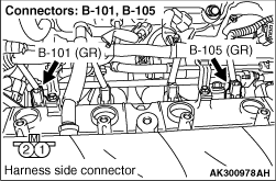
- B-101 (No. 1 injector connector).
- B-105 (No. 4 injector connector).
Q.
Are the check results normal?
Go to Step 8 .
Repair or replace.
|
|
|
- Check No. 1 and No. 4 Injector itself (Refer to ).
|
|
|
Q.
Is the check result normal?
|
|
Q.
Is the check result normal?
Go to Step 10 .
Repair or replace.
|
|
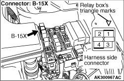
- Check intermediate connector C-116, and repair if necessary If intermediate connector is normal, harness between B-15X (terminal No. 1) engine control relay connector and B-101 (terminal No. 1) No. 1 injector connector.
- Check intermediate connector C-116, and repair if necessary If intermediate connector is normal, harness between B-15X (terminal No. 1) engine control relay connector and B-105 (terminal No. 1) No. 4 injector connector.
- Check power supply line for damage.
Q.
Are the check results normal?
Go to Step 11 .
Repair or replace.
|
|
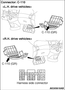
- Check harness between B-101 (terminal No. 2) No. 1 injector connector and C-110 (terminal No. 1) engine-ECU <M/T> connector or engine-A/T-ECU <A/T> connector.
- Check harness between B-105 (terminal No. 2) No. 4 injector connector and C-110 (terminal No. 21) engine-ECU <M/T> connector or engine-A/T-ECU <A/T> connector.
- Check power supply line for damage.
Q.
Are the check results normal?
Go to Step 12 .
Repair.
|
|
|
- Check purge control solenoid valve itself (Refer to GROUP 17 - Emission Control System - Evaporative Emission Control System- Purge Control Solenoid Valve ).
|
|
|
Q.
Is the check result normal?
|
|
|
Replace purge control solenoid valve.
|
|
|
|
|
|
- Fuel pressure measurement (Refer to Fuel Pressure Test ).
|
|
|
Q.
Is the check result normal?
|
|
|
Replace engine-ECU <M/T> or engine-A/T-ECU <A/T>.
|
|
|
|


