|
|
If the A/C compressor does not operate, the A/C compressor circuit system or the CAN bus lines may be defective.
|
|
|
- Malfunction of the Engine-ECU <M/T> or Engine-A-M/T-ECU <Automated manual transmission>
- Malfunction of the A/C compressor
- Malfunction of the engine control relay
|
|
|
Use the M.U.T.-III to diagnose the CAN bus lines.
|
|
|
Q.
Is the check result normal?
|
|
|
 Repair the CAN bus line (Refer to GROUP 54C, Troubleshooting Repair the CAN bus line (Refer to GROUP 54C, Troubleshooting  ). ).
|
|
|
|
|
|
Check whether the air conditioner sets a diagnosis code or not.
|
|
|
Q.
Is the check result normal?
|
|
|
Refer to diagnosis code chart .
|
|
|
|
|
|
Check that the following service data display contents are normal. (Refer to ).
|
|
|
- Item 11: A/C Pressure sensor
|
|
|
Q.
Is the check result normal?
|
|
|
Inspection Procedure 9: Refer to A/C pressure sensor system .
|
|
|
|
|
|
(1)Turn the ignition switch to the "ON" position.
|
|
|
(2)Set the blower switch to the position other than OFF.
|
|
|
Q.
Does the blower motor work normally?
|
|
|
Refer to Inspection procedure 2 "Blower fan and motor do not turn ."
|
|
|
|
|
Q.
Is the check result normal?
 Go to Step 6. Go to Step 6.
Repair the connector.
|
|
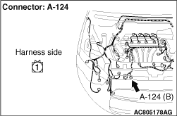
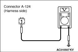
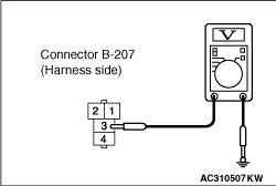
(1)Disconnect the connector, and measure at the wiring harness side.
|
|
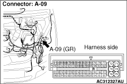
(2)Disconnect A-09 Engine-ECU <M/T> or Engine-A-M/T-ECU <Automated manual transmission> and earth terminal 95.
|
|
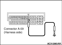
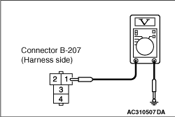
(3)Voltage between terminal 1 and body earth.
OK: System voltage
Q.
Is the check result normal?
Go to Step 15.
Go to Step 7.
|
|
Q.
Is the check result normal?
Go to Step 8.
Repair the connector.
|
|
|
Refer to GROUP 13A, On-vehicles Service - Engine Control Relay Continuity Check . <134>
|
|
|
Refer to GROUP 13B, On-vehicles Service - Engine Control Relay Continuity Check . <135>
|
|
|
Q.
Is the engine control relay in good condition?
|
|
|
Replace the engine control relay.
|
|
|
|
|
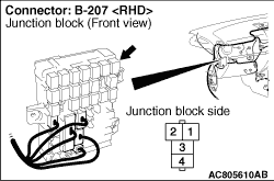
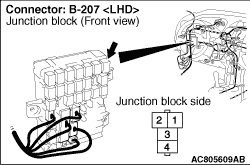
(1)Remove the relay, and measure at the relay block side.
|
|
(2)Voltage between terminal 3 and body earth.
OK: System voltage
Q.
Is the check result normal?
Go to Step 11.
Go to Step 10.
|
|
| note |
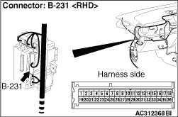
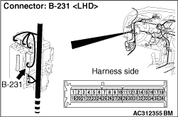
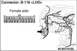
Prior to the wiring harness inspection, check junction block connectors B-208, B-231, B-212 and intermediate connector B-118, and repair if necessary.
|
- Check the A/C compressor relay power supply line for open circuit.
Q.
Is the check result normal?
The trouble can be an intermittent malfunction (Refer to GROUP 00, How to Cope with Intermittent Malfunction ).
Repair the wiring harness.
|
|
(1)Remove the relay, and measure at the relay block side.
|
|
(2)Measure the voltage between terminal 1 and body earth.
OK: System voltage
Q.
Is the check result normal?
Go to Step 13.
Go to Step 12.
|
|
| note |
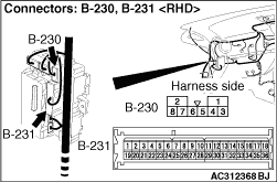
Prior to the wiring harness inspection, check junction block connectors B-231, B-230, and repair if necessary.
|
- Check the A/C compressor relay power supply line for open circuit.
Q.
Is the check result normal?
The trouble can be an intermittent malfunction (Refer to GROUP 00, How to Cope with Intermittent Malfunction ).
Repair the wiring harness.
|
|
| note |
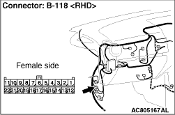
Prior to the wiring harness inspection, check junction block connectors B-231, intermediate connector B-118, and repair if necessary.
|
- Check the A/C compressor relay power supply line for open circuit.
Q.
Is the check result normal?
Go to Step 14.
Repair the wiring harness.
|
|
| note |
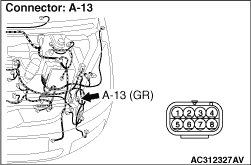
Prior to the wiring harness inspection, check junction block connectors B-231, intermediate connector A-13 and B-118, and repair if necessary.
|
- Check the A/C compressor power supply line for open circuit.
Q.
Is the check result normal?
The trouble can be an intermittent malfunction (Refer to GROUP 00, How to Cope with Intermittent Malfunction ).
Repair the wiring harness.
|
|
|
Q.
Is the check result normal?
|
|
|
Replace the A/C compressor.
|
|
|
|
|
|
Q.
Is the refrigerant level correct?
|
|
|
Correct the refrigerant level (Refer to ).
|
|
|
|
|
|
Check that the A/C works normally.
|
|
|
Q.
Is the check result normal?
|
|
|
This diagnosis is complete.
|
|
|
|
|
|
Replace the engine-ECU <M/T> or the engine-A-M/T-ECU <Automated manual transmission>.
|
|
|
|
)
)
)
)
)
)
)
)
)
)
)
)
)
)
)
)
)
)
)
)