|
|
If the A/C-ECU is not energised, the power supply or earth system to the ECU may be defective.
|
|
|
- Malfunction of the semi automatic air conditioner control panel assembly (A/C-ECU)
- Damaged wiring harness or connectors
|
|
Q.
Is the check result normal?
 Go to Step 2. Go to Step 2.
 Repair the connector. Repair the connector.
|
|
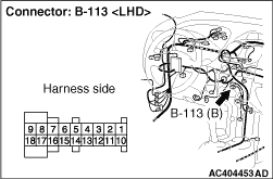
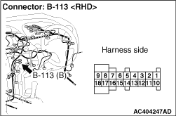
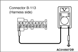
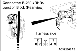
(1)Disconnect the connector, and measure at the wiring harness side.
(2)Turn the ignition switch to the ON position.
|
|
(3)Measure the voltage between terminal 18 and body earth.
OK: System voltage
Q.
Is the check result normal?
Go to Step 4.
Go to Step 3.
|
|
| note |
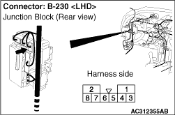
Prior to the wiring harness inspection, check junction block connector B-230, and repair if necessary.
|
- Check the A/C-ECU power supply line for open circuit.
Q.
Is the check result normal?
The trouble can be an intermittent malfunction (Refer to GROUP 00, How to Cope with Intermittent Malfunction  ). ).
Repair the wiring harness.
|
|
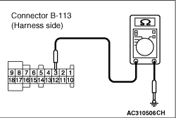
(1)Disconnect the connector, and measure at the wiring harness side.
|
|
(2)Continuity between terminal 3 and body earth
OK: Continuity (Less than 2Ω)
Q.
Is the check result normal?
Replace the A/C-ECU.
Go to Step 5.
|
|
- Check the A/C-ECU earth line for open circuit.
Q.
Is the check result normal?
The trouble can be an intermittent malfunction (Refer to GROUP 00, How to Cope with Intermittent Malfunction ).
Repair the wiring harness.
|
)
)
)
)
)
)
)