Schedule
|
Warning type
|
Warning criteria
|
EU 1
|
Elapsed time (month)
|
Every 12 elapsed month
|
Driving distance (miles)
|
Every 9,000 miles of driving distance
|
Driving distance (km)
|
Every 15,000 km of driving distance
|
EU 2 (initial condition)
|
Elapsed time (month)
|
Every 12 elapsed month
|
Driving distance (miles)
|
Every 12,500 miles of driving distance
|
Driving distance (km)
|
Every 20,000 km of driving distance
|
Optional INT
|
The optional schedule can be set. (Only M.U.T.-III can
be set.)
|
OFF Display
|
Without function. "OFF" is displayed on the information
display.
|
Function OFF
|
Without function (Only M.U.T.-III can be set.)
|
|
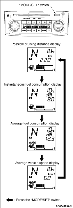
By gently pressing the "MODE/SET" switch on the radio with CD player, the fuel
consumption information is displayed on the information display. Each gentle pressing of the "MODE/SET"
switch with the fuel consumption information displayed, the display shifts in the order of the "possible
cruising distance", "instantaneous fuel consumption", "average fuel consumption" or "average
vehicle speed."
|
|
These gauges use a stepping motor as the drive mechanism for the indicators (called the
"movement"). Compared with conventional movements, the torque for driving the indicators is much
greater for superior indicator accuracy and more stable response. The indicator position displayed
is determined as the microcontroller circuit in the gauge controls the stepping motor. In conventional
gauges, the indicator revolves 360°
in response to 360°
driving controls.
However, a stepping motor is designed so that the indicator revolves only 45°, even
in response to a drive control of 360°. The 45°
drive control must be repeated
to make the indicator rotate 360°. Thus, at a position 45°
away from the indicator
display position, there will be an identical control.
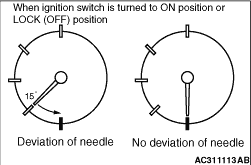
As a result, in the case of a great impact such as from an accident when the indicator
becomes misaligned, if the ignition is switched on to start driving while the indicator is misaligned, the
indicator will function while misaligned. Thus, to return the indicator to the normal position
in case this happens, when the ignition is switched on, the indicator positions are reset to
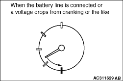
their respective positions after the battery line is connected after it is cut. After the battery
line is cut and reconnected, the indicators simply return to the zero position. The same operation
is performed after voltage is restored if gauge functions are lost because of a voltage drop
from cranking or the like. Furthermore, the indicator only returns 45°
after the ignition
is switched on or the lock is turned off. The indicator is not moved if it is not misaligned.
|
Diagnosis code No.
|
Diagnosis item
|
B1011
|
Ambient Temperature Sensor Circuit Low
|
B1012
|
Ambient Temperature Sensor Circuit High
|
B1200
|
Malfunction odometer
|
B1201
|
Trouble of fuel information
|
U1073
|
Bus Off
|
U1100
|
Engine-ECU or engine-A-M/T-ECU time-out (related to engine)
|
U1101
|
Engine-A-M/T-ECU time-out (related to automated manual transmission)
|
U1102
|
ABS-ECU or TCL/ASC-ECU CAN communication time-out
|
U1106
|
Electric power steering-ECU CAN communication time-out
|
U1109
|
ETACS-ECU time-out
|
U1112
|
SRS-ECU time-out
|
U1120
|
Failure information on engine-ECU or engine-A/T-ECU (Related
to Engine)
|
U1121
|
Failure information on engine-A-M/T-ECU (related to automated
manual transmission)
|
U1122
|
Failure information on ABS-ECU or TCL/ASC-ECU
|
U1132
|
Failure information on SRS-ECU
|
U1206
|
Flag invalid
|
 .
.)
)
)
)
)