|
|
Check the operation of the room lamp and luggage compartment lamp with conditions below.
|
|
|
- Check if the room lamp illuminates when the room lamp switch is turned to
the ON position.
- Check if the room lamp and the luggage compartment lamp illuminate when any of the
door is opened with the room lamp switch in the "DOOR" position.
|
|
|
Q.
Which of the following cases is applied to the trouble symptom?
|
|
|
The room lamp does not illuminate when the room lamp switch is turned to the "ON" position. : Go to Step 2 : Go to Step 2
|
|
|
|
|
|
The room lamp and the luggage compartment lamp do not illuminate when any of the door
is opened with the room lamp switch in the "DOOR" position. : Go to Step 4
|
|
|
|
|
|
The room lamp or the luggage compartment lamp does not illuminate when any of the door
is opened with the room lamp switch in the "DOOR" position. : Go to Step 24
|
|
|
|
|
|
The room lamp and luggage compartment lamp do not illuminate with the room lamp switch
in the position either "ON" or "DOOR." : Go to Step 31
|
|
|
|
|
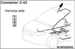
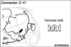
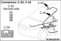
Q.
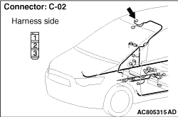
Is room lamp connector C-02 in good condition?
 Go to Step 3. Go to Step 3.
 Repair or replace the damaged component(s). Repair or replace the damaged component(s).
|
|
|
Check the earth wires for open circuit.
|
|
| note |
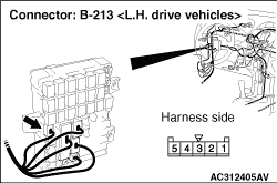
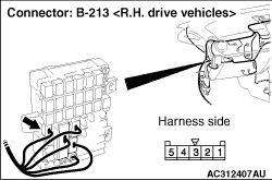
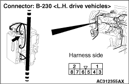
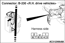
Prior to the wiring harness inspection, check intermediate connector C-34 and junction
block connectors B-213 and B-230, and repair if necessary.
|
Q.
Is the wiring harness wire between room lamp connector C-02 terminal No.1 and body
earth in good condition?
Replace the defective room lamp or luggage compartment lamp.
Repair the wiring harness.
|
|
|
Check the input signals from the driver’s door switch to the ETACS-ECU.
|
|
|
OK: Normal condition are displayed for the items.
|
|
|
Q.
Is the check result normal?
|
|
|
YES <LH drive vehicles> : Go to Step 10.
|
|
|
|
|
|
YES <RH drive vehicles> : Go to Step 5.
|
|
|
|
|
|
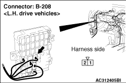
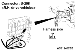
NO : Check the input signals from the driver’s door switch (Refer to GROUP
54B, Input Signal Procedure  <LH drive vehicles> or <RH
drive vehicles>). <LH drive vehicles> or <RH
drive vehicles>).
|
|
|
|
|
|
Check the input signals from the steering lock switch to the ETACS-ECU.
|
|
|
OK: Normal condition are displayed for the items.
|
|
|
Q.
Is the check result normal?
|
|
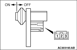
Check the continuity at the key reminder switch.
Status of ignition key
|
Tester connection
|
Specified condition
|
Removed
|
4 - 9
|
Continuity exists (2 Ω or less)
|
Inserted
|
4 - 9
|
No continuity
|
Q.
Is the check result normal?
Go to Step 7.
Replace the key reminder switch.
|
|
Q.
Is the check result normal?
Go to Step 8.
Repair the defective connector.
|
|
Are the room lamp and the luggage compartment lamp in good condition?
Q.
Is the check result normal?
Go to Step 9.
Repair the wiring harness.
|
|
|
Check the earth wires for open circuit.
|
|
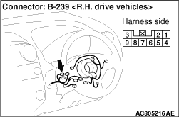
Q.
Are the wiring harnesses between B-239 key reminder switch (terminal 4) and body earth
in good condition?
Go to Step 10.
Repair the wiring harness.
|
|
|
Check the input signals from the driver’s door unlock switch to the ETACS-ECU.
|
|
|
OK: Normal condition are displayed for the items.
|
|
|
Q.
Is the check result normal?
|
|
|
NO <vehicles without dead lock system> : Go to Step 11.
|
|
|
|
|
|
NO <vehicles with dead lock system> : Go to Step 12.
|
|
|
|
|
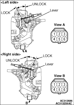
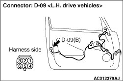
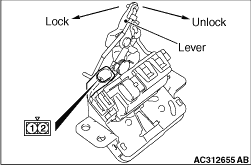
Check the continuity at the driver’s door unlock switch.
|
|
ACTUATOR SWITCH CHECK <DRIVER’S SIDE
(LH DRIVE VEHICLES)>
Lever position
|
Tester connection
|
Specified condition
|
At the "LOCK" position
|
1 - 2
|
Continuity exists (2 Ω or less)
|
At the "UNLOCK" position
|
1 - 3
|
|
|
|
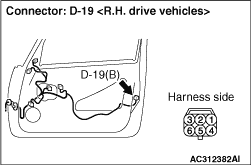
ACTUATOR SWITCH CHECK <DRIVER’S SIDE
(RH DRIVE VEHICLES)>
Lever position
|
Tester connection
|
Specified condition
|
At the "LOCK" position
|
2 - 3
|
Continuity exists (2 Ω or less)
|
At the "UNLOCK" position
|
1 - 3
|
|
Q.
Is the check result normal?
Go to Step 13.
Replace the driver’s unlock switch.
|
|
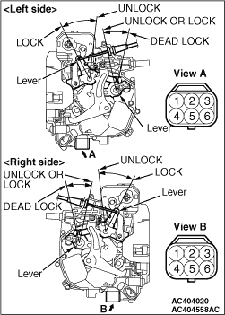
Check the continuity at the driver’s door unlock switch.
|
|
ACTUATOR SWITCH CHECK <DRIVER’S SIDE>
Lever position
|
Tester connection
|
Specified condition
|
At the "LOCK" position
|
2 - 3
|
Continuity exists (2 Ω or less)
|
At the "DEAD LOCK" position
|
1 - 2
|
At the "UNLOCK" position
|
1 - 3
|
|
Q.
Is the check result normal?
Go to Step 13.
Replace the driver’s unlock switch.
|
|
Q.
Is the check result normal?
Go to Step 14.
Repair the defective connector.
|
|
|
Check the earth wires for open circuit.
|
|
Q.
Is the check result normal?
Go to Step 15.
Repair the wiring harness.
|
|
|
Check the input lines for open circuit and short circuit.
|
|
Q.
Is the check result normal?
Go to Step 16.
Repair the wiring harness.
|
|
|
Check the input signals from each of the all door switches (except driver’s door)
to the ETACS-ECU.
|
|
|
- All door (except driver’s door): Open
|
|
|
OK: Normal condition are displayed for the items.
|
|
|
Q.
Is the check result normal?
|
|
|
Check the continuity at each of the door switches (excluding the driver’s door).
|
|
|
|
Switch position
|
Tester connection
|
Specified condition
|
Released (ON)
|
2 - switch body, 3 - switch body
|
Continuity exists (2 Ω or less)
|
Depressed (OFF)
|
2 - switch body, 3 - switch body
|
No continuity
|
|
Q.
Is the check result normal?
Go to Step 18.
Replace the defective door switch.
|
|
Q.
Is the check result normal?
Go to Step 19.
Repair the defective connector.
|
|
|
Check the input lines for open circuit and short circuit.
|
|
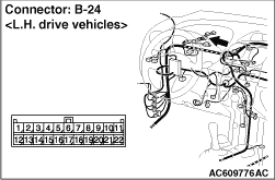
| note |
Prior to the wiring harness inspection, check joint connector B-24, and repair if necessary.
|
Q.
Is the check result normal?
Go to Step 20.
Repair the wiring harness.
|
|
|
Check the continuity at the tailgate switch.
|
|
|
|
Lever position
|
Tester connection
|
Specified condition
|
At the "LOCK" position
|
1 - 2
|
No continuity
|
At the "UNLOCK" position
|
1 - 2
|
Continuity exists (2 Ω or less)
|
|
Q.
Is the check result normal?
Go to Step 21.
Replace the tailgate switch.
|
|
Q.
Is the check result normal?
Go to Step 22.
Repair the defective connector.
|
|
|
Check the input lines for open circuit and short circuit.
|
|
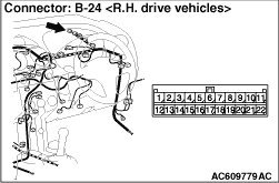
| note |
Prior to the wiring harness inspection, check joint connectors B-24 and intermediate connector
E-11, and repair if necessary.
|
Q.
Is the check result normal?
Go to Step 23.
Repair the wiring harness.
|
|
|
Check the earth wires for open circuit.
|
|
Q.
Is the check result normal?
Go to Step 34.
Repair the wiring harness.
|
|
|
Check if the luggage compartment lamp illuminates.
|
|
|
Q.
Does the luggage compartment lamp illuminate?
|
|
Q.
Is the check result normal?
Go to Step 26.
Repair the defective connector.
|
|
|
Check that the room lamp bulb are in good condition.
|
|
|
Q.
Is the check result normal?
|
|
|
Replace the bulb(s) of the defective lamp.
|
|
|
|
|
|
Check the input lines for open circuit and short circuit.
|
|
| note |
Prior to the wiring harness inspection, check intermediate connector C-34, and repair
if necessary.
|
Q.
Is the check result normal?
Replace the room lamp.
Repair the wiring harness.
|
|
Q.
Is the check result normal?
Go to Step 29.
Repair the defective connector.
|
|
|
Check that the luggage compartment lamp bulb are in good condition.
|
|
|
Q.
Is the check result normal?
|
|
|
Replace the bulb(s) of the defective lamp.
|
|
|
|
|
|
Check the input lines for open circuit and short circuit.
|
|
| note |
Prior to the wiring harness inspection, check intermediate connector B-117 and joint connector
B-24, and repair if necessary.
|
Q.
Is the check result normal?
Replace the luggage compartment lamp.
Repair the wiring harness.
|
|
Q.
Is the check result normal?
Go to Step 32.
Repair the defective connector.
|
|
|
Check the input lines for short circuit.
|
|
| note |
Prior to the wiring harness inspection, check intermediate connector C-34 and joint connector
B-24, and repair if necessary.
|
Q.
Is the check result normal?
Go to Step 33 .
Repair the wiring harness.
|
|
|
Check the power supply line for open circuit.
|
|
Q.
Is the check result normal?
Replace the junction block.
Repair the wiring harness.
|
|
|
Check that the room lamp and luggage compartment lamp illuminate normally.
|
|
|
Q.
Is the check result normal?
|
|
|
The trouble can be an intermittent malfunction (Refer to GROUP 00, How to use
Troubleshooting/inspection Service Points - How to Cope with Intermittent
Malfunction ).
|
|
|
|
|
|
Replace the ETACS-ECU. Then perform the variant coding (Refer to GROUP 00, Precautions
Before Service - How to Perform Variant Coding ).
|
|
|
|
)
)
)
)
)
)
)
)
)
)
)
)
)
)
)
)
)
)
)
)
)
)
)
)
)
)
)
)
)
)
)
)
)
)
)
)