|
|
Q.
Which turn-signal lamp fails to illuminate correctly?
|
|
|
Front turn-signal lamp : Go to Step 2. : Go to Step 2.
|
|
|
|
|
|
Side turn-signal lamp : Go to Step 9.
|
|
|
|
|
|
Rear turn-signal lamp : Go to Step 16.
|
|
|
|
|
|
All lamps on the right side do not illuminate. : Go to Step 23.
|
|
|
|
|
|
All lamps on the left side do not illuminate. : Go to Step 24.
|
|
|
|
|
Q.
Is the check result normal?
 Go to Step 3. Go to Step 3.
 Repair the defective connector. Go to Step 25. Repair the defective connector. Go to Step 25.
|
|
|
Check the bulb(s) of the defective lamp.
|
|
|
Q.
Is the check result normal?
|
|
|
Replace the bulb(s) of the defective lamp. Go to Step 25.
|
|
|
|
|
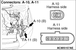
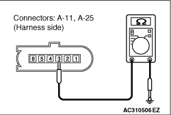
(1)Disconnect the connector, and measure at the wiring harness side.
|
|
(2)Resistance measurement between the defective lamp connector terminal and body earth.
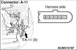
- Resistance between A-11 front combination lamp (turn: LH) connector terminal
No.3 and body earth
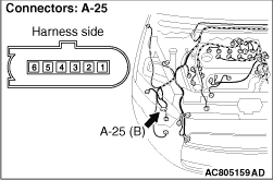
- Resistance between A-25 front combination lamp (turn: RH) connector terminal No.3
and body earth
OK: Continuity exists (2 Ω or less)
Q.
Is the check result normal?
Go to Step 6.
Go to Step 5.
|
|
- Check the earth wires for open circuit.
Q.
Is the check result normal?
The trouble can be an intermittent malfunction (Refer to GROUP 00 - How
to use Troubleshooting/inspection Service Points - How to Cope with Intermittent
Malfunction  ). Go to Step 25. ). Go to Step 25.
Repair the wiring harness. Go to Step 25.
|
|
Q.
Is the check result normal?
Go to Step 7.
Repair the defective connector. Go to Step 25.
|
|
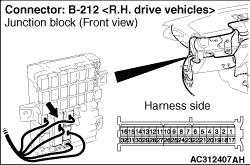
| note |
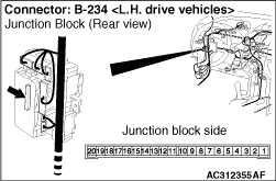
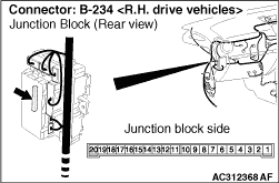
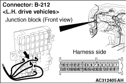
Prior to the wiring harness inspection, check junction block connector B-212, and repair
if necessary.
|
- Check the output lines for open circuit.
Q.
Is the check result normal?
Go to Step 8.
Repair the wiring harness. Go to Step 25.
|
|
|
Check that the front turn-signal lamps illuminate normally.
|
|
|
Q.
Is the check result normal?
|
|
|
The trouble can be an intermittent malfunction (Refer to GROUP 00 - How
to use Troubleshooting/inspection Service Points - How to Cope with Intermittent
Malfunction ). Go to Step 25.
|
|
|
|
|
|
Replace the front combination lamp. Go to Step 25.
|
|
|
|
|
Q.
Is the check result normal?
Go to Step 10.
Repair the defective connector. Go to Step 25.
|
|
|
Check the bulb(s) of the defective lamp.
|
|
|
Q.
Is the check result normal?
|
|
|
Replace the bulb(s) of the defective lamp. Go to Step 25.
|
|
|
|
|
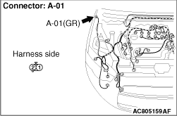
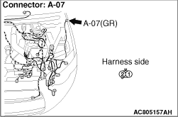
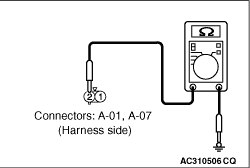
(1)Disconnect the connector, and measure at the wiring harness side.
|
|
(2)Resistance measurement between the defective lamp connector terminal and body earth.
- Resistance between A-07 side turn-signal lamp (LH) connector terminal No.2
and body earth
- Resistance between A-01 side turn-signal lamp (RH) connector terminal No.2 and body
earth
OK: Continuity exists (2 Ω or less)
Q.
Is the check result normal?
Go to Step 13.
Go to Step 12.
|
|
- Check the earth wires for open circuit.
Q.
Is the check result normal?
The trouble can be an intermittent malfunction (Refer to GROUP 00 - How
to use Troubleshooting/inspection Service Points - How to Cope with Intermittent
Malfunction ).
Repair the wiring harness. Go to Step 25.
|
|
Q.
Is the check result normal?
Go to Step 14.
Repair the defective connector. Go to Step 25.
|
|
| note |
Prior to the wiring harness inspection, check junction block connector B-212, and repair
if necessary.
|
- Check the output lines for open circuit.
Q.
Is the check result normal?
Go to Step 15.
Repair the wiring harness. Go to Step 25.
|
|
|
Check that the side turn-signal lamps illuminate normally.
|
|
|
Q.
Is the check result normal?
|
|
|
The trouble can be an intermittent malfunction (Refer to GROUP 00 - How
to use Troubleshooting/inspection Service Points - How to Cope with Intermittent
Malfunction ). Go to Step 25.
|
|
|
|
|
|
Replace the side turn-signal lamp. Go to Step 25.
|
|
|
|
|
Q.
Is the check result normal?
Go to Step 17.
Repair the defective connector. Go to Step 25.
|
|
|
Check the bulb(s) of the defective lamp.
|
|
|
Q.
Is the check result normal?
|
|
|
Replace the bulb(s) of the defective lamp. Go to Step 25.
|
|
|
|
|
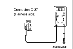
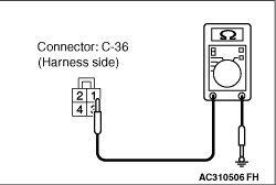
(1)Disconnect the connector, and measure at the wiring harness side.
|
|
(2)Resistance measurement between the defective lamp connector terminal and body earth.
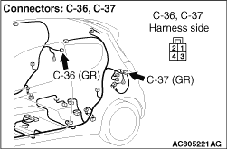
- Resistance between C-37 rear combination lamp (turn: LH) connector terminal No.2 and body
earth
- Resistance between C-36 rear combination lamp (turn: RH) connector terminal No.1 and body
earth
OK: Continuity exists (2 Ω or less)
Q.
Is the check result normal?
Go to Step 20.
Go to Step 19.
|
|
- Check the earth wires for open circuit.
Q.
Is the check result normal?
The trouble can be an intermittent malfunction (Refer to GROUP 00 - How
to use Troubleshooting/inspection Service Points - How to Cope with Intermittent
Malfunction ). Go to Step 25.
Repair the wiring harness. Go to Step 25.
|
|
Q.
Is the check result normal?
Go to Step 21.
Repair the defective connector. Go to Step 25.
|
|
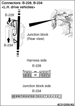
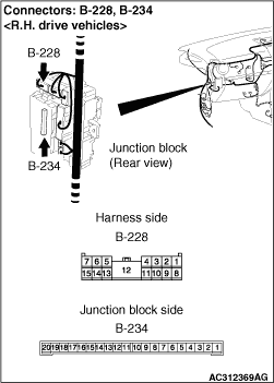
| note |
Prior to the wiring harness inspection, check junction block connector B-228, and repair
if necessary.
|
- Check the output lines for open circuit.
Q.
Is the check result normal?
Go to Step 22.
Repair the wiring harness. Go to Step 25.
|
|
|
Check that the rear turn-signal lamps illuminate normally.
|
|
|
Q.
Is the check result normal?
|
|
|
The trouble can be an intermittent malfunction (Refer to GROUP 00 - How
to use Troubleshooting/inspection Service Points - How to Cope with Intermittent
Malfunction ). Go to Step 25.
|
|
|
|
|
|
Replace the rear combination lamp. Go to Step 25.
|
|
|
|
|
| note |
Prior to the wiring harness inspection, check junction block connectors B-212 and B-228,
and repair if necessary.
|
- Check the output lines for short circuit.
Q.
Is the check result normal?
Go to Step 25.
Repair the wiring harness. Go to Step 25.
|
|
| note |
Prior to the wiring harness inspection, check junction block connectors B-212 and B-228,
and repair if necessary.
|
- Check the output lines for short circuit.
Q.
Is the check result normal?
Go to Step 25.
Repair the wiring harness. Go to Step 25.
|
|
|
Check if diagnosis code No.B1740 or B1741 is set.
|
|
|
Q.
Is the diagnosis code set?
|
|
|
Replace the ETACS-ECU. Then perform the variant coding and write the VIN data
(Refer to GROUP 00, Precautions Before Service - How to Perform Variant Coding ).
|
|
|
|
|
|
The procedure is complete.
|
|
|
|
)
)
)
)
)
)
)
)
)
)
)
)
)
)
)
)
)
)
)
)
)
)
)
)