|
|
The ETACS-ECU operates this function in accordance with the input signals below.
|
|
|
- Tail lamp switch
- Headlamp switch
- Rear fog lamp switch
|
|
|
If the rear fog lamps (both right and left) do not illuminate, these input signal circuit(s) or the ETACS-ECU may be defective.
|
|
|
- Malfunction of the column switch
- Malfunction of the rear fog lamp switch
- Malfunction of the ETACS-ECU
- Damaged harness wires and connectors
|
|
|
Check that ETACS-ECU sets a diagnosis code.
|
|
|
Q.
Is the diagnosis code set?
|
|
|
 Refer to diagnosis code chart Refer to diagnosis code chart  . .
|
|
|
|
|
|
Check that the tail lamps and headlamps illuminate normally.
|
|
|
Q.
Is the check result normal?
|
|
|
 Check the tail lamps and the headlamps (Refer to trouble symptom chart ). Check the tail lamps and the headlamps (Refer to trouble symptom chart ).
|
|
|
|
|
|
Check the input signals below, which are related to the rear fog lamps.
|
|
|
- Ignition switch: ON
- Rear fog lamp switch: ON
|
|
|
OK: Normal conditions are displayed for all the items.
|
|
|
Q.
Is the check result normal?
|
|
|
All the signals are received normally. : Go to Step 4. : Go to Step 4.
|
|
|
|
|
|
The ignition switch (IG1) signal is not received. : Refer to inspection procedure J-3 "The ignition switch (IG1) signal is not received ."
|
|
|
|
|
|
The rear fog lamp switch signal is not received. : Refer to inspection procedure J-6 "The rear fog lamp switch signal is not received ."
|
|
|
|
|
|
Perform the actuator test for the ETACS-ECU, and check that the rear fog lamps illuminate normally.
|
|
|
- Item 35: Rear fog lamp: OFF
- Item 36: Rear fog lamp: ON
|
|
|
Q.
Is the check result normal?
|
|
Q.
Is the check result normal?
Go to Step 6.
Repair the defective connector.
|
|
|
Refer to GROUP 54A - rear fog lamp .
|
|
|
Q.
Is the check result normal?
|
|
|
Replace the rear fog lamp relay.
|
|
|
|
|
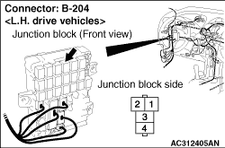
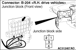
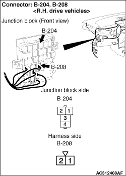
(1)Remove the rear fog lamp relay, and measure at the relay box side.
|
|
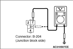
(2)Check the voltage between the rear fog lamp relay connector and body earth.
- Voltage between B-204 rear fog lamp relay connector terminal No.1 and body earth
- Voltage between B-204 rear fog lamp relay connector terminal No.3 and body earth
OK: System voltage
Q.
Is the check result normal?
Go to Step 9.
Go to Step 8.
|
|
| note |
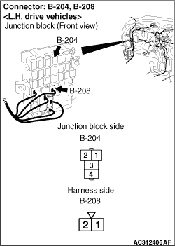
Prior to the wiring harness inspection, check the junction block connector B-208, and repair if necessary.
|
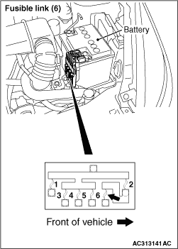
- Check the power supply line from the fusible link (6) for open circuit.
Q.
Is the check result normal?
The trouble can be an intermittent malfunction (Refer to GROUP 00 - How to use Troubleshooting/inspection Service Points - How to Cope with Intermittent Malfunction ).
Repair the wiring harness.
|
|
Q.
Is the check result normal?
Go to Step 10.
Repair the defective connector.
|
|
|
Check the bulb(s) of the defective lamp.
|
|
|
Q.
Is the check result normal?
|
|
|
Replace the bulb(s) of the defective lamp.
|
|
|
|
|
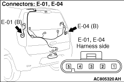
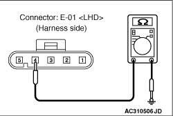
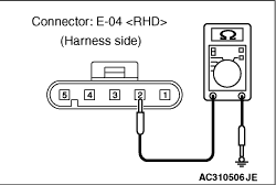
(1)Disconnect the connector, and measure at the wiring harness side.
|
|
(2)Check the resistance between E-01 rear fog lamp relay connector <LH drive vehicles> terminal No.4 or E-04 rear fog lamp relay connector <RH drive vehicles> connector terminal No.2 and body earth.
OK: Continuity exists (2 Ω or less)
Q.
Is the check result normal?
Go to Step 13.
Go to Step 12.
|
|
- Check the earth wires for open circuit.
Q.
Is the check result normal?
The trouble can be an intermittent malfunction (Refer to GROUP 00 - How to use Troubleshooting/inspection Service Points - How to Cope with Intermittent Malfunction ).
Repair the wiring harness.
|
|
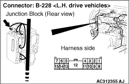
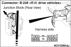
| note |
Prior to the wiring harness inspection, check junction block connector B-228, and repair if necessary.
|
- Check the output lines for open circuit.
Q.
Is the check result normal?
Go to Step 14.
Repair the wiring harness.
|
|
Q.
Is the check result normal?
Go to Step 15.
Repair the defective connector.
|
|
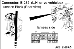
| note |
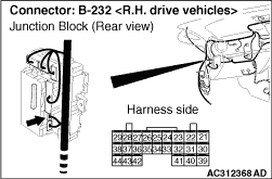
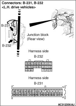
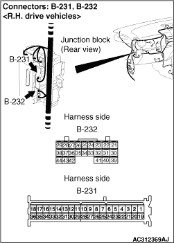
Prior to the wiring harness inspection, check the junction block connector B-231, and repair if necessary.
|
- Check the output lines for open circuit.
Q.
Is the check result normal?
Go to Step 16.
Repair the wiring harness.
|
|
|
Check that the rear fog lamps illuminate normally.
|
|
|
Q.
Is the check result normal?
|
|
|
The trouble can be an intermittent malfunction (Refer to GROUP 00 - How to use Troubleshooting/inspection Service Points - How to Cope with Intermittent Malfunction ).
|
|
|
|
|
|
Replace the ETACS-ECU. Then perform the variant coding and write the VIN data (Refer to GROUP 00, Precautions Before Service - How to Perform Variant Coding ).
|
|
|
|
)
)
)
)
)
)
)
)
)
)
)
)
)
)
)
)
)