|
|
Check that ETACS-ECU sets a diagnosis code.
|
|
|
Q.
Is the diagnosis code set?
|
|
|
 Refer to diagnosis code chart Refer to diagnosis code chart  . .
|
|
|
|
|
|
Check the input signal from the headlamp (low-beam) switch.
|
|
|
(1)Turn the ignition switch to the "ON" position.
|
|
|
(2)Turn the headlamp (low-beam) switch to the ON position.
|
|
Item No.
|
Item name
|
Normal condition
|
04
|
Low beam lamp
|
ON
|
30
|
Ignition Switch (IG1)
|
ON
|
|
OK: Normal conditions are displayed for all the items.
|
|
|
Q.
Is the check result normal?
|
|
|
YES <All the signals are received normally.> : Go to Step 3. : Go to Step 3.
|
|
|
|
|
|
NO <The ignition switch (IG1) signal is not received.> : Refer to inspection procedure J-3 "The ignition switch (IG1) signal is not received ."
|
|
|
|
|
|
NO <The headlamp (low-beam) switch signal is not received.> : Refer to Inspection Procedure J-1 "The column switch (lighting and wiper switch) signal is not received ."
|
|
|
|
|
|
Perform the actuator test of the ETACS-ECU, and check that the headlamps (low-beam) work normally.
|
|
|
- Item 03: Head lamp low: OFF
- Item 04: Head lamp low: ON
|
|
|
Q.
Is the check result normal?
|
|
Q.
Is the check result normal?
Go to Step 5.
 Repair the defective connector. Repair the defective connector.
|
|
|
Refer to GROUP 54A - Headlamp .
|
|
|
Q.
Is the check result normal?
|
|
|
Replace the headlamp relay (LO).
|
|
|
|
|
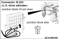
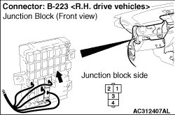
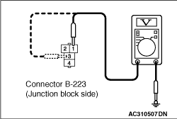
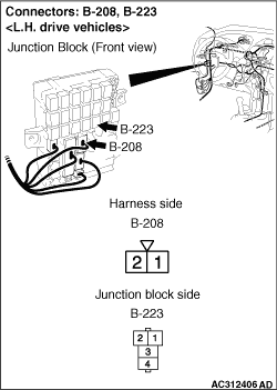
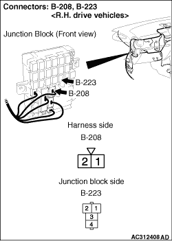
(1)Remove the headlamp relay (LO), and measure at the junction block side.
|
|
(2)Voltage between B-223 headlamp relay (LO) connector terminal Nos.1, 3 and body earth
OK: System voltage
Q.
Is the check result normal?
Go to Step 8.
Go to Step 7.
|
|
| note |
Prior to the wiring harness inspection, check the junction block connector B-208, and repair if necessary.
|
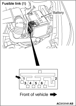
- Check the power supply line from the fusible link (1) for open circuit.
Q.
Is the check result normal?
The trouble can be an intermittent malfunction (Refer to GROUP 00 - How to use Troubleshooting/inspection Service Points - How to Cope with Intermittent Malfunction ).
Repair the wiring harness.
|
|
Q.
Is the check result normal?
Go to Step 9.
Repair the defective connector.
|
|
|
Check that the low-beam headlamps illuminate normally.
|
|
|
Q.
Is the check result normal?
|
|
|
The trouble can be an intermittent malfunction (Refer to GROUP 00 - How to use Troubleshooting/inspection Service Points - How to Cope with Intermittent Malfunction ).
|
|
|
|
|
|
Replace the ETACS-ECU. Then perform the variant coding and write the VIN data (Refer to GROUP 00, Precautions Before Service - How to Perform Variant Coding ).
|
|
|
|
)
)
)
)
)
)
)
)
)