|
| caution |
The strand end of the twist wire should be within 10 cm from the connector. For details refer to  . .
|
|
|
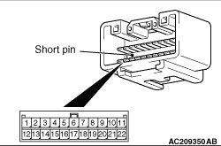
When checking the joint connector, ensure that its wiring harness side and its short pins are not damaged.
Q.
Are the check results normal?
 Go to Step 2. Go to Step 2.
 Repair a defective connector or replace the joint connector. Repair a defective connector or replace the joint connector.
|
|
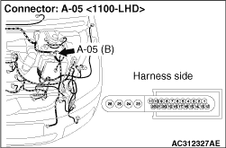
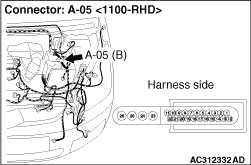
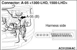
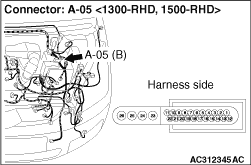
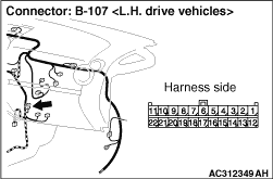
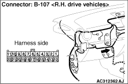
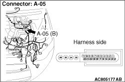
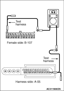
(1)Disconnect the joint connector (CAN2) and the ABS-ECU connector, and measure at the wiring harness side.
(2)Ignition switch: OFF (LOCK)
(3)
| caution |
When measuring the resistance, disconnect the negative battery terminal. For details refer to .
|
Ensure that the negative battery terminal is disconnected.
|
|
(4)Continuity between B-107 joint connector (CAN2) terminal No.11 and A-05 ABS-ECU connector terminal No.12
OK: 2 ohms or less
|
|
(5)Continuity between B-107 joint connector (CAN2) terminal No.22 and A-05 ABS-ECU connector terminal No.1
OK: 2 ohms or less
| caution |
Strictly observe the specified wiring harness repair procedure. For details refer to .
|
Q.
Are the check results normal?
<All the resistances measure 2 Ω or less> Power supply to the ABS-ECU may be suspected. Diagnose the ABS system. Refer to .
<Either or all of the voltages measure more than 2 Ω> Repair the wiring harness between the joint connector (CAN2) and the ABS-ECU connector.
|
)
)
)
)
)
)
)
)
)
)
)
)
)