|
| caution |
The strand end of the twist wire should be within 10 cm from the connector. For details refer to  . .
|
|
|
When checking the joint connector, ensure that its wiring harness side is not damaged.
Q.
Are the check results normal?
 Go to Step 2. Go to Step 2.
 Repair a defective connector or replace the joint connector. Repair a defective connector or replace the joint connector.
|
|
(1)Disconnect the joint connector (CAN1) and the intermediate connector, and measure at the wiring harness side.
(2)Ignition switch: OFF (LOCK)
(3)
| caution |
When measuring the resistance, disconnect the negative battery terminal. For details refer to .
|
Ensure that the negative battery terminal is disconnected.
|
|
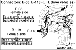
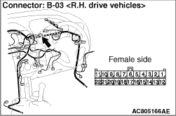
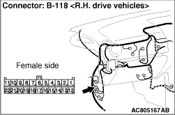
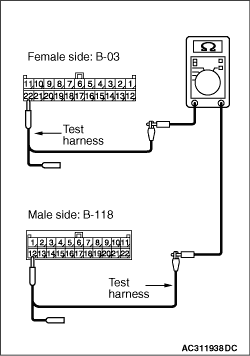
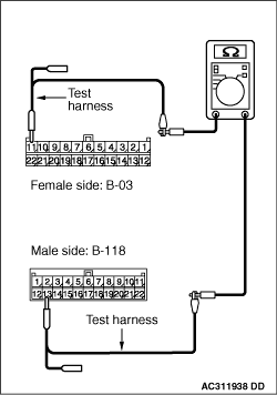
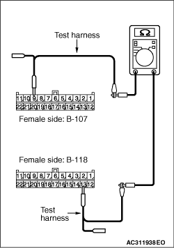
(4)Continuity between B-118 intermediate connector terminal No.12 and B-03 joint connector (CAN1) terminal No.22
OK: 2 Ω or less
|
|
(5)Continuity between B-118 intermediate connector terminal No.13 and B-03 joint connector (CAN1) terminal No.11
OK: 2 Ω or less
| caution |
Strictly observe the specified wiring harness repair procedure. For details refer to .
|
Q.
Are the check results normal?
<All the voltages measure 2 Ω or less> Go to Step 3
.
<Either or all of the resistances measure more than 2 Ω> Repair the wiring harness between joint connector (CAN1) and the intermediate connector.
|
|
| caution |
The strand end of the twist wire should be within 10 cm from the connector. For details refer to .
|
When checking the joint connector, ensure that its wiring harness side is not damaged.
Q.
Is the check result normal?
Go to Step 4.
Repair a defective connector or replace the joint connector (front wiring harness assembly).
|
|
(1)Disconnect the joint connector (CAN2) and the intermediate connector, and measure at the wiring harness side.
(2)Ignition switch: OFF (LOCK)
(3)
| caution |
When measuring the resistance, disconnect the negative battery terminal. For details refer to .
|
Ensure that the negative battery terminal is disconnected.
|
|
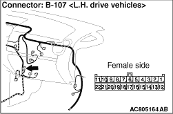
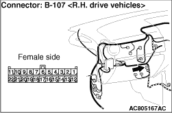
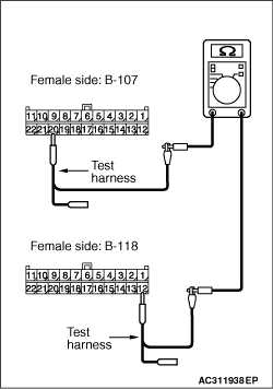
(4)Continuity between B-107 joint connector (CAN2) terminal No.9 and B-118 intermediate connector terminal No.13
OK: 2 Ω or less
|
|
(5)Continuity between B-107 joint connector (CAN2) terminal No.20 and B-118 intermediate connector terminal No.12
OK: 2 Ω or less
| caution |
Strictly observe the specified wiring harness repair procedure. For details refer to .
|
Q.
Are the check results normal?
<All the resistances measure 2 Ω or less> Follow diagnosis item 15 "Diagnose the lines from the main bus line to the engine-ECU <M/T> or engine-A-M/T-ECU <Automated manual transmission>" (Refer to ), diagnosis item 16 "Diagnose the lines between CAN main bus line and the ABS-ECU (Refer to ) <vehicles without active stability control system> or diagnosis item 17 "Diagnose the lines between CAN main bus line and the TCL/ASC-ECU" (Refer to ) <vehicles with TCL/ASC system>.
<Either or all of the resistances measure more than 2 Ω> Repair the wiring harness between joint connector (CAN2) and the intermediate connector.
|
)
)
)
)
)
)
)
)
)
)
)
)
)