|
| caution |
The strand end of the twist wire should be within 10 cm from the connector. For details refer to  . .
|
Q.
Is the check result normal?
 Go to Step 2. Go to Step 2.
 Repair the connector, and then go to Step 2. Repair the connector, and then go to Step 2.
|
|
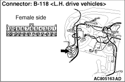
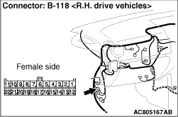
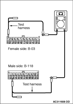
(1)Disconnect the connector, and measure at its female-side intermediate connector (at the front wiring harness side).
(2)Ignition switch: OFF (LOCK)
(3)
| caution |
When measuring the resistance, disconnect the negative battery terminal. For details refer to .
|
Ensure that the negative battery terminal is disconnected.
|
|
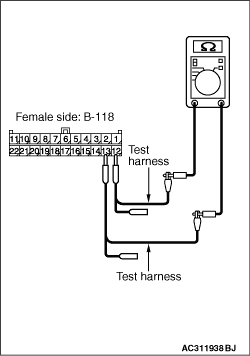
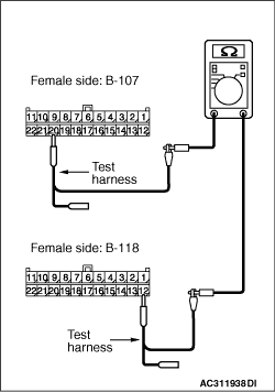
(4)Resistance between B-118 intermediate connector terminal Nos.12 and 13
OK: 120 ± 20 Ω
Q.
Is the check result normal?
<Within 120 ± 20 Ω> Go to Step 3 .
<Not within 120 ± 20 Ω> Go to Step 8 .
|
|
| caution |
The strand end of the twist wire should be within 10 cm from the connector. For details refer to .
|
|
|
When checking the joint connector, ensure that its wiring harness side is not damaged.
Q.
Are the check results normal?
Go to Step 4.
Repair the connector, or replace the joint connector. Then go to Step 2.
|
|
(1)Disconnect the connector, and measure at the wiring harness side.
(2)Ignition switch: OFF (LOCK)
(3)
| caution |
When measuring the resistance, disconnect the negative battery terminal. For details refer to .
|
Ensure that the negative battery terminal is disconnected.
|
|
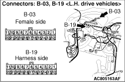
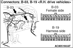
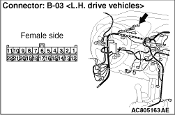
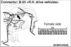
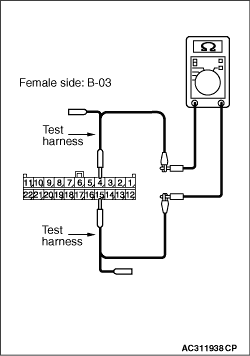
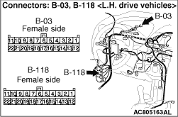
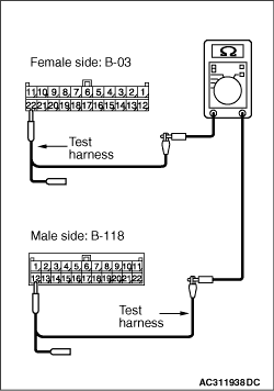
(4)Resistance between B-03 joint connector (CAN1) terminal Nos.4 and 15
OK: 120 ± 20 Ω
Q.
Is the check result normal?
<Within 120 ± 20 Ω> Go to Step 7 .
<Not within 120 ± 20 Ω> Go to Step 5 .
|
|
(1)Disconnect the joint connector (CAN1) and the combination meter connector, and measure at the wiring harness side.
(2)Ignition switch: OFF (LOCK)
(3)
| caution |
When measuring the resistance, disconnect the negative battery terminal. For details refer to .
|
Ensure that the negative battery terminal is disconnected.
|
|
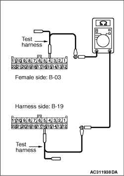
(4)Continuity between B-03 joint connector (CAN1) terminal No.4 and B-19 combination meter connector terminal No.16
OK: 2 Ω or less
|
|
(5)Continuity between B-03 joint connector (CAN1) terminal No.15 and B-19 combination meter connector terminal No.15
OK: 2 Ω or less
| caution |
Strictly observe the specified wiring harness repair procedure. For details refer to .
|
Q.
Are the check results normal?
<All the voltages measure 2 Ω or less> Go to Step 6
.
<Either or all of the voltages measure more than 2 Ω> Repair the wiring harness between joint connector (CAN1) and the combination meter connector, and then go to Step 2.
|
|
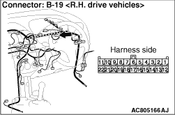
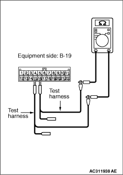
(1)Remove the combination meter, and measure at the equipment side.
|
|
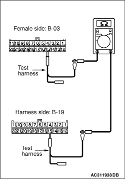
(2)Resistance between B-19 combination meter connector terminal Nos.15 and 16
OK: 120 ± 20 Ω
Q.
Is the check result normal?
<Within 120 ± 20 Ω> Go to Step 2 .
<Not within 120 ± 20 Ω> Replace the combination meter, perform the variant coding (Refer to GROUP 00, Precautions Before Service - How to Perform Variant Coding ), and then go to Step 2.
|
|
(1) Disconnect the joint connector (CAN1) and the intermediate connector, and measure at the wiring harness side.
(2)Ignition switch: OFF (LOCK)
(3)
| caution |
When measuring the resistance, disconnect the negative battery terminal. For details refer to .
|
Ensure that the negative battery terminal is disconnected.
|
|
(4)Continuity between B-118 intermediate connector terminal No.12 and B-03 joint connector (CAN1) terminal No.22
OK: 2 Ω or less
|
|
(5)Continuity between B-118 intermediate connector terminal No.13 and B-03 joint connector (CAN1) terminal No.11
OK: 2 Ω or less
| caution |
Strictly observe the specified wiring harness repair procedure. For details refer to .
|
Q.
Are the check results normal?
<All the voltages measure 2 Ω or less> Go to Step 2
.
<Either or all of the voltages measure more than 2 Ω> Repair the wiring harness between joint connector (CAN1) and the intermediate connector, and then go to Step 2.
|
|
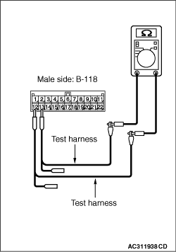
(1)Disconnect the connector, and measure at its male-side intermediate connector (at the instrument panel wiring harness side).
(2)Ignition switch: OFF (LOCK)
(3)
| caution |
When measuring the resistance, disconnect the negative battery terminal. For details refer to .
|
Ensure that the negative battery terminal is disconnected.
|
|
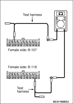
(4)Resistance between B-118 intermediate connector terminal Nos.12 and 13
OK: 120 ± 20 Ω
Q.
Is the check result normal?
<Within 120 ± 20 Ω> Go to Step 14 .
<Not within 120 ± 20 Ω> Go to Step 9 .
|
|
| caution |
The strand end of the twist wire should be within 10 cm from the connector. For details refer to .
|
When checking the joint connector, ensure that its wiring harness side is not damaged.
Q.
Are the check results normal?
Go to Step 10.
Repair the connector, or replace the joint connector (front wiring harness assembly). Then go to Step 8.
|
|
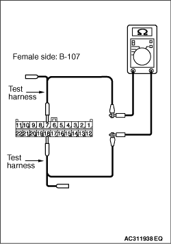
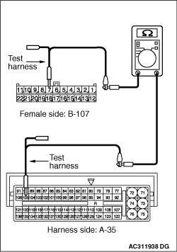
(1)Disconnect the connector, and measure at the wiring harness side.
(2)Ignition switch: OFF (LOCK)
(3)
| caution |
When measuring the resistance, disconnect the negative battery terminal. For details refer to .
|
Ensure that the negative battery terminal is disconnected.
|
|
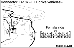
(4)Resistance between B-107 joint connector (CAN2) terminal Nos.7 and 18
OK: 120 ± 20 Ω
Q.
Is the check result normal?
<Within 120 ± 20 Ω> Go to Step 13 .
<Not within 120 ± 20 Ω> Go to Step 11 .
|
|
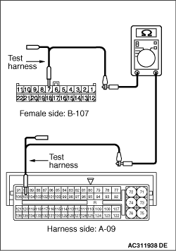
(1)Disconnect the engine-ECU <M/T> or engine-A-M/T-ECU <Automated manual transmission> connector and the joint connector (CAN2), and measure at the wiring harness side.
(2)Ignition switch: OFF (LOCK)
(3)
| caution |
When measuring the resistance, disconnect the negative battery terminal. For details refer to .
|
Ensure that the negative battery terminal is disconnected.
|
|
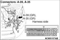
(4)Continuity between B-107 joint connector (CAN2) terminal No.7 and A-09 engine-ECU <M/T> or engine-A-M/T-ECU <Automated manual transmission> connector terminal No.105 <except 1500-T/C>
OK: 2 Ω or less
|
|
(5)Continuity between B-107 joint connector (CAN2) terminal No.18 and A-09 engine-ECU <M/T> or engine-A-M/T-ECU <Automated manual transmission> connector terminal No.106 <except 1500-T/C>
OK: 2 Ω or less
|
|
(6)Continuity between B-107 joint connector (CAN2) terminal No.7 and A-35 engine-ECU connector terminal No.105 <1500-T/C>
OK: 2 Ω or less
|
|
(7)Continuity between B-107 joint connector (CAN2) terminal No.18 and A-35 engine-ECU connector terminal No.106 <1500-T/C>
OK: 2 Ω or less
| caution |
Strictly observe the specified wiring harness repair procedure. For details refer to .
|
Q.
Are the check results normal?
<All the voltages measure 2 Ω or less> Go to Step 12
.
<Either or all of the voltages measure more than 2 Ω> Repair the wiring harness between the engine-ECU <M/T> or engine-A-M/T-ECU <Automated manual transmission> connector and the intermediate connector, and then go to Step 8
.
|
|
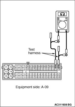
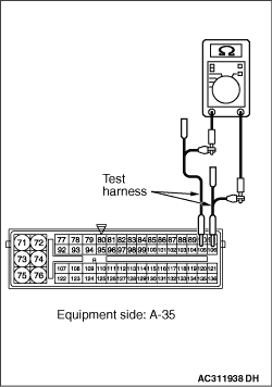
(1)Remove the engine-ECU <M/T> or engine-A-M/T-ECU <Automated manual transmission>, and measure at the equipment side.
|
|
(2)Resistance at A-09 engine-ECU <M/T> or engine-A-M/T-ECU <Automated manual transmission> connector terminal Nos.105 and 106 <except 1500-T/C>
OK: 120 ± 20 Ω
|
|
(3)Resistance at A-35 engine-ECU connector terminal Nos.105 and 106 <1500-T/C>
OK: 120 ± 20 Ω
Q.
Is the check result normal?
<Within 120 ± 20 Ω> Go to Step 8 .
<Not within 120 ± 20 Ω> Replace the engine-ECU <M/T> or engine-A-M/T-ECU <Automated manual transmission>, perform the variant coding (Refer to GROUP 00, Precautions Before Service - How to Perform Variant Coding ), and then go to Step 8.
|
|
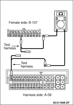
(1)Disconnect the joint connector (CAN2) and the intermediate connector, and measure at the wiring harness side.
(2)Ignition switch: OFF (LOCK)
(3)
| caution |
When measuring the resistance, disconnect the negative battery terminal. For details refer to .
|
Ensure that the negative battery terminal is disconnected.
|
|
(4)Continuity between B-118 intermediate connector terminal No.12 and B-107 joint connector (CAN2) terminal No.20
OK: 2 Ω or less
|
|
(5)Continuity between B-118 intermediate connector terminal No.13 and B-107 joint connector (CAN2) terminal No.9
OK: 2 Ω or less
| caution |
Strictly observe the specified wiring harness repair procedure. For details refer to .
|
Q.
Are the check results normal?
<All the voltages measure 2 Ω or less> Go to Step 8
.
<Either or all of the voltages measure more than 2 Ω> Repair the wiring harness between joint connector (CAN2) and the intermediate connector, and then go to Step 8.
|
|
| caution |
The strand end of the twist wire should be within 10 cm from the connector. For details refer to .
|
Q.
Is the check result normal?
Go to Step 15.
Repair the connector, or replace the joint connector. Then go to Step 15.
|
|
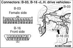
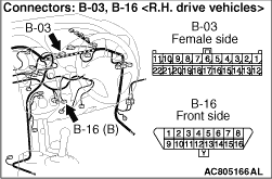
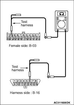
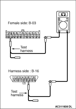
(1)Disconnect the joint connector (CAN1) and the diagnosis connector, and measure at the wiring harness side.
(2)Ignition switch: OFF (LOCK)
(3)
| caution |
When measuring the resistance, disconnect the negative battery terminal. For details refer to .
|
Ensure that the negative battery terminal is disconnected.
|
|
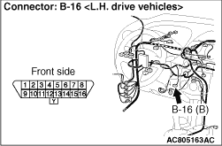
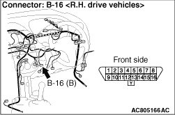
(4)Continuity between B-03 joint connector (CAN1) terminal No.10 and B-16 diagnosis connector terminal No.6
OK: 2 Ω or less
|
|
(5)Continuity between B-03 joint connector (CAN1) terminal No.21 and B-16 diagnosis connector terminal No.14
OK: 2 Ω or less
| caution |
Strictly observe the specified wiring harness repair procedure. For details refer to .
|
Q.
Are the check results normal?
YES <all the resistances measure 2 Ω or less: When any repair done> : Retest the system.
YES <all the resistances measure 2 Ω or less: When no repair done> : It is determined that there is an intermittent malfunction such as poor engaged connector(s) or open circuit (Refer to GROUP 00, How to Cope with Intermittent Malfunction ).
<Either of the resistances measures more than 2 Ω or all the resistances measure more than 2 Ω> : Repair the wiring harness between joint connector (CAN1) and the diagnosis connector.
|
)
)
)
)
)
)
)
)
)
)
)
)
)
)
)
)
)
)
)
)
)
)
)
)
)
)
)
)
)
)
)
)
)
)
)
)
)