|
| caution |
The strand end of the twist wire should be within 10 cm from the connector. For details refer to  . .
|
Q.
Is the check result normal?
 Go to Step 2. Go to Step 2.
 Repair the defective connector. Repair the defective connector.
|
|
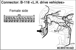
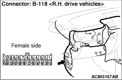
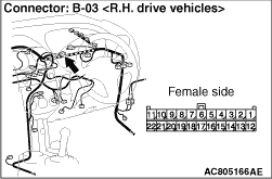
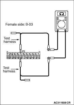
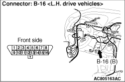
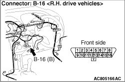
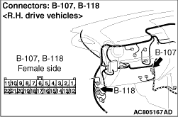
(1)Disconnect the connector, and measure at its female-side intermediate connector (at the front wiring harness side).
(2)Ignition switch: OFF (LOCK)
(3)
| caution |
When measuring the resistance, disconnect the negative battery terminal. For details refer to .
|
Ensure that the negative battery terminal is disconnected.
|
|
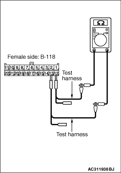
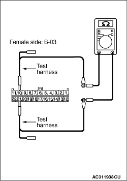
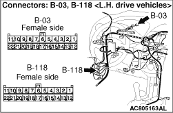
(4)Resistance between B-118 intermediate connector terminal Nos.12 and 13
OK: 120 ± 20 Ω
Q.
Is the check result normal?
<Within 120 ± 20 Ω> Go to Step 3.
<Not within 120 ± 20 Ω> Go to Step 20.
|
|
| caution |
The strand end of the twist wire should be within 10 cm from the connector. For details refer to .
|
|
|
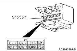
When checking the joint connector, ensure that its wiring harness side and its short pins are not damaged.
Q.
Is the check result normal?
Go to Step 4.
Repair a defective connector or replace the joint connector.
|
|
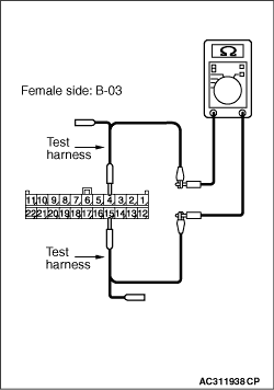
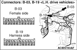
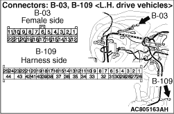
(1)Disconnect the connector, and measure at the wiring harness side.
(2)Ignition switch: OFF (LOCK)
(3)
| caution |
When measuring the resistance, disconnect the negative battery terminal. For details refer to .
|
Ensure that the negative battery terminal is disconnected.
|
|
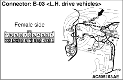
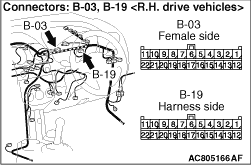
(4)Resistance between B-03 joint connector (CAN1) terminal Nos.4 and 15
OK: 120 ± 20 Ω
|
|
(5)Resistance between B-03 joint connector (CAN1) terminal Nos.5 and 16
OK: 1 kΩ or more
|
|
(6)Resistance between B-03 joint connector (CAN1) terminal Nos.7 and 18
OK: 1 kΩ or more
|

|
(7)Resistance between B-03 joint connector (CAN1) terminal Nos.9 and 20
OK: 1 kΩ or more
|

|
(8)Resistance between B-03 joint connector (CAN1) terminal Nos.10 and 21
OK: 1 kΩ or more
Q.
Are the check results normal?
YES <all of the measurement results are within the normal value> : Go to Step 19. : Go to Step 19.
NO <The resistance between terminal Nos.4 and 15 is less than 120 ± 20 Ω> : Go to Step 5.
NO <The resistance between terminal Nos.5 and 16 is less than 1 kΩ> : Go to Step 8.
NO <The resistance between terminal Nos.7 and 18 is less than 1 kΩ> : Go to Step 11.
NO <The resistance between terminal Nos.9 and 20 is less than 1 kΩ> : Go to Step 14.
NO <The resistance between terminal Nos.10 and 21 is less than 1 kΩ> : Go to Step 17.
|
|
| caution |
The strand end of the twist wire should be within 10 cm from the connector. For details refer to .
|
Q.
Is the check result normal?
Go to Step 6.
Repair the defective connector.
|
|
(1)Disconnect the joint connector (CAN1) and the combination meter connector, and measure at the wiring harness side.
(2)Ignition switch: OFF (LOCK)
(3)
| caution |
When measuring the resistance, disconnect the negative battery terminal. For details refer to .
|
Ensure that the negative battery terminal is disconnected.
|
|
(4)Continuity between B-03 joint connector (CAN1) terminal Nos.4 and 15
OK: More than 2 Ω
| caution |
Strictly observe the specified wiring harness repair procedure. For details refer to .
|
Q.
Is the check result normal?
<More than 2 Ω> Go to Step 7.
<2 Ω or less> Repair the wiring harness between joint connector (CAN1) and the combination meter connector.
|
|
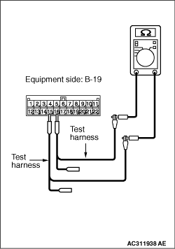
(1)Remove the combination meter, and measure at the equipment side.
|
|
(2)Resistance between B-19 combination meter connector terminal Nos.15 and 16
OK: 120 ± 20 Ω
Q.
Is the check result normal?
<Within 120 ± 20 Ω> It is determined that there is an intermittent malfunction such as poor engaged connector(s) or open circuit (Refer to GROUP 00, How to Cope with Intermittent Malfunction ).
<Not within 120 ± 20 Ω> Replace the combination meter. Then perform the variant coding (Refer to GROUP 00, Precautions Before Service - How to Perform Variant Coding ).
|
|
| caution |
The strand end of the twist wire should be within 10 cm from the connector. For details refer to .
|
Q.
Is the check result normal?
Go to Step 9.
Repair the defective connector.
|
|
(1)Disconnect the joint connector (CAN1) and the ETACS-ECU connector, and measure at the wiring harness side.
(2)Ignition switch: OFF (LOCK)
(3)
| caution |
When measuring the resistance, disconnect the negative battery terminal. For details refer to .
|
Ensure that the negative battery terminal is disconnected.
|
|
(4)Continuity between B-03 joint connector (CAN1) terminal Nos.5 and 16
OK: More than 2 Ω
| caution |
Strictly observe the specified wiring harness repair procedure. For details refer to .
|
Q.
Is the check result normal?
<More than 2 Ω> Go to Step 10.
<2 Ω or less> Repair the wiring harness between joint connector (CAN1) and the ETACS-ECU connector.
|
|
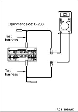
(1)Remove the ETACS-ECU, and measure at the equipment side.
|
|
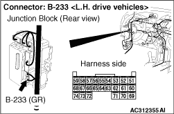
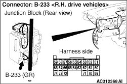
(2)Resistance between B-233 ETACS-ECU connector terminal Nos.56 and 65
OK: 1 kΩ or more
Q.
Is the check result normal?
<1 kΩ or more> It is determined that there is an intermittent malfunction such as poor engaged connector(s) or open circuit (Refer to GROUP 00, How to Cope with Intermittent Malfunction ).
<Less than 1 kΩ> Replace the ETACS-ECU. Then perform the variant coding (Refer to GROUP 00, Precautions Before Service - How to Perform Variant Coding ).
|
|
| caution |
The strand end of the twist wire should be within 10 cm from the connector. For details refer to .
|
Q.
Is the check result normal?
Go to Step 12.
Repair the defective connector.
|
|
(1)Disconnect the joint connector (CAN1) and the SRS-ECU connector, and measure at the wiring harness side.
(2)Ignition switch: OFF (LOCK)
(3)
| caution |
When measuring the resistance, disconnect the negative battery terminal. For details refer to .
|
Ensure that the negative battery terminal is disconnected.
|
|
(4)Continuity between B-03 joint connector (CAN1) terminal Nos.7 and 18
OK: More than 2 Ω
| caution |
Strictly observe the specified wiring harness repair procedure. For details refer to .
|
Q.
Is the check result normal?
<More than 2 Ω> Go to Step 13.
<2 Ω or less> Repair the wiring harness between joint connector (CAN1) and the SRS-ECU connector.
|
|
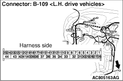
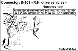
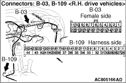
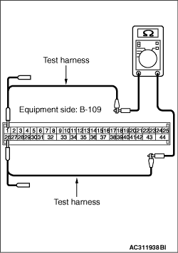
(1)Remove the SRS-ECU, and measure at the equipment side.
|
|
(2)Resistance between B-109 SRS-ECU connector terminal Nos.26 and 1
OK: 1 kΩ or more
Q.
Is the check result normal?
<1 kΩ or more> It is determined that there is an intermittent malfunction such as poor engaged connector(s) or open circuit (Refer to GROUP 00, How to Cope with Intermittent Malfunction ).
<Less than 1 kΩ> Replace the SRS-ECU.
|

|
| caution |
The strand end of the twist wire should be within 10 cm from the connector. For details refer to .
|
Q.
Is the check result normal?
Go to Step 15.
Repair the defective connector.
|
|
(1)Disconnect the joint connector (CAN1) and the steering wheel sensor connector, and measure at the wiring harness side.
(2)Ignition switch: OFF (LOCK)
(3)
| caution |
When measuring the resistance, disconnect the negative battery terminal. For details refer to .
|
Ensure that the negative battery terminal is disconnected.
|
|
(4)Continuity between B-03 joint connector (CAN1) terminal Nos.9 and 20
OK: More than 2 Ω
| caution |
Strictly observe the specified wiring harness repair procedure. For details refer to .
|
Q.
Is the check result normal?
<More than 2 Ω> Go to Step 16.
<2 Ω or less> Repair the wiring harness between joint connector (CAN1) and the steering wheel sensor connector.
|
|
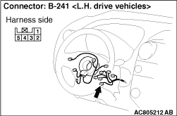
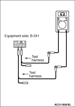
(1)Remove the steering wheel sensor, and measure at the equipment side.
|
|
(2)Resistance between B-241 steering wheel sensor connector terminal Nos.3 and 4
OK: 1 kΩ or more
Q.
Is the check result normal?
<1 kΩ or more> It is determined that there is an intermittent malfunction such as poor engaged connector(s) or open circuit (Refer to GROUP 00, How to Cope with Intermittent Malfunction ).
<Less than 1 kΩ> Replace the steering wheel sensor.
|
|
| caution |
The strand end of the twist wire should be within 10 cm from the connector. For details refer to .
|
Q.
Is the check result normal?
Go to Step 18.
Repair the defective connector.
|
|
(1)Disconnect the joint connector (CAN1), and measure at the wiring harness side.
(2)Ignition switch: OFF (LOCK)
(3)
| caution |
When measuring the resistance, disconnect the negative battery terminal. For details refer to .
|
Ensure that the negative battery terminal is disconnected.
|
|
(4)Continuity between B-03 joint connector (CAN1) terminal Nos.10 and 21
OK: More than 2 Ω
| caution |
Strictly observe the specified wiring harness repair procedure. For details refer to .
|
Q.
Is the check result normal?
<More than 2 Ω> It is determined that there is an intermittent malfunction such as poor engaged connector(s) or open circuit (Refer to GROUP 00, How to Cope with Intermittent Malfunction ).
<2 Ω or less> Repair the wiring harness between joint connector (CAN1) and the diagnosis connector.
|
|
(1)Disconnect the joint connector (CAN1) and the intermediate connector, and measure at the wiring harness side.
(2)Ignition switch: OFF (LOCK)
(3)
| caution |
When measuring the resistance, disconnect the negative battery terminal. For details refer to .
|
Ensure that the negative battery terminal is disconnected.
|

|
(4)Continuity between B-03 joint connector (CAN1) terminal Nos.11 and 22
OK: More than 2 Ω
| caution |
Strictly observe the specified wiring harness repair procedure. For details refer to .
|
Q.
Is the check result normal?
<More than 2 Ω> It is determined that there is an intermittent malfunction such as poor engaged connector(s) or open circuit (Refer to GROUP 00, How to Cope with Intermittent Malfunction ).
<2 Ω or less> Repair the wiring harness between joint connector (CAN1) and the intermediate connector.
|
|
| caution |
The strand end of the twist wire should be within 10 cm from the connector. For details refer to .
|
When checking the joint connector, ensure that its wiring harness side is not damaged.
Q.
Is the check result normal?
Go to Step 21.
Repair a defective connector or replace the joint connector (front wiring harness assembly).
|
|
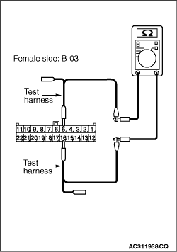
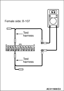
(1)Disconnect the connector, and measure at the wiring harness side.
(2)Ignition switch: OFF (LOCK)
(3)
| caution |
When measuring the resistance, disconnect the negative battery terminal. For details refer to .
|
Ensure that the negative battery terminal is disconnected.
|

|
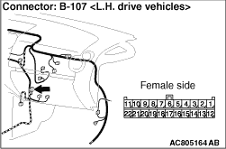
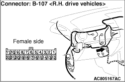
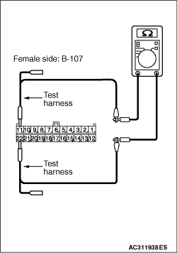
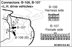
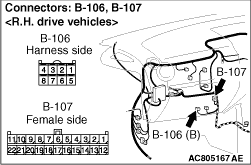
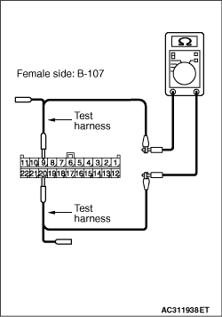
(4)Resistance between B-107 joint connector (CAN2) terminal Nos.7 and 18
OK: 120 ± 20 Ω
|
|
(5)Resistance between B-107 joint connector (CAN2) terminal Nos.11 and 22
OK: 1 kΩ or more
|
|
(6)Resistance between B-107 joint connector (CAN2) terminal Nos.10 and 21
OK: 1 kΩ or more
|
|
(7)Resistance between B-107 joint connector (CAN2) terminal Nos.8 and 19
OK: 1 kΩ or more
Q.
Are the check results normal?
YES <all of the measurement results are within the normal value> : Go to Step 34.
NO <The resistance between terminal Nos.7 and 18 is less than 120 ± 20 Ω> : Go to Step 22.
NO <The resistance between terminal Nos.11 and 22 is less than 1 kΩ> : Go to Step 25.
NO <The resistance between terminal Nos.10 and 21 is less than 1 kΩ> : Go to Step 28.
NO <The resistance between terminal Nos.8 and 19 is less than 1 kΩ> : Go to Step 31.
|
|
| caution |
The strand end of the twist wire should be within 10 cm from the connector. For details refer to .
|
Q.
Is the check result normal?
Go to Step 23.
Repair the defective connector.
|
|
(1)Disconnect the joint connector (CAN2) and the engine-ECU <M/T> or engine-A-M/T-ECU <Automated manual transmission> connector, and measure at the wiring harness side.
(2)Ignition switch: OFF (LOCK)
(3)
| caution |
When measuring the resistance, disconnect the negative battery terminal. For details refer to .
|
Ensure that the negative battery terminal is disconnected.
|
|
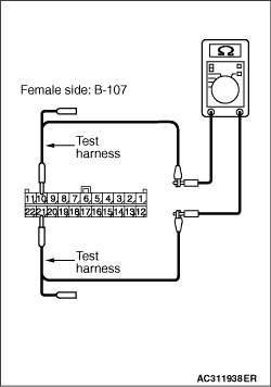
(4)Continuity between B-107 joint connector (CAN2) terminal Nos.7 and 18
OK: More than 2 Ω
| caution |
Strictly observe the specified wiring harness repair procedure. For details refer to .
|
Q.
Is the check result normal?
<More than 2 Ω> Go to Step 24.
<2 Ω or less> Repair the wiring harness between joint connector (CAN2) and the engine-ECU <M/T> or engine-A-M/T-ECU <Automated manual transmission> connector.
|
|
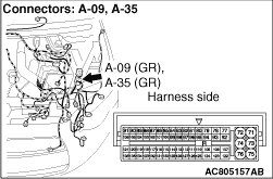
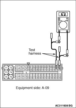
(1)Remove the engine-ECU <M/T> or engine-A-M/T-ECU <Automated manual transmission>, and measure at the equipment side.
|
|
(2)Resistance at A-09 engine-ECU <M/T> or engine-A-M/T-ECU <Automated manual transmission> connector terminal Nos.105 and 106 <except 1500-T/C>
OK: 120 ± 20 Ω
|
|
(3)A-35 engine-ECU <M/T> connector terminal Nos.105 and 106 <1500-T/C>
OK: 120 ± 20 Ω
Q.
Is the check result normal?
<Within 120 ± 20 Ω> It is determined that there is an intermittent malfunction such as poor engaged connector(s) or open circuit (Refer to GROUP 00, How to Cope with Intermittent Malfunction ).
<Not within 120 ± 20 Ω> Replace the engine-ECU <M/T> or engine-A-M/T-ECU <Automated manual transmission>. Then perform the variant coding (Refer to GROUP 00, Precautions Before Service - How to Perform Variant Coding ).
|
|
| caution |
The strand end of the twist wire should be within 10 cm from the connector. For details refer to .
|
Q.
Is the check result normal?
Go to Step 26.
Repair the defective connector.
|
|
(1)Disconnect the joint connector (CAN2) and the TCL/ASC-ECU connector, and measure at the wiring harness side.
(2)Ignition switch: OFF (LOCK)
(3)
| caution |
When measuring the resistance, disconnect the negative battery terminal. For details refer to .
|
Ensure that the negative battery terminal is disconnected.
|
|
(4)Continuity between B-107 joint connector (CAN2) terminal Nos.11 and 22
OK: More than 2 Ω
| caution |
Strictly observe the specified wiring harness repair procedure. For details refer to .
|
Q.
Is the check result normal?
<More than 2 Ω> Go to Step 27.
<2 Ω or less> Repair the wiring harness between joint connector (CAN2) and the TCL/ASC-ECU connector.
|
|
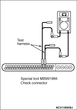
(1)Connect special tool MB991984 to the TCL/ASC-ECU connector, and measure by using the check connector (connect the ECU side only).
|
|
(2)Resistance between special tool MB991984 check connector terminal Nos.38 and 39.
OK: 1 kΩ or more
Q.
Is the check result normal?
<1 kΩ or more> It is determined that there is an intermittent malfunction such as poor engaged connector(s) or open circuit (Refer to GROUP 00, How to Cope with Intermittent Malfunction ).
<Less than 1 kΩ> Replace the TCL/ASC-ECU. Then perform the variant coding (Refer to GROUP 00, Precautions Before Service - How to Perform Variant Coding ).
|
|
| caution |
The strand end of the twist wire should be within 10 cm from the connector. For details refer to .
|
Q.
Is the check result normal?
Go to Step 29.
Repair the defective connector.
|
|
(1)Disconnect the joint connector (CAN2) and the electric power steering-ECU connector, and measure at the wiring harness side.
(2)Ignition switch: OFF (LOCK)
(3)
| caution |
When measuring the resistance, disconnect the negative battery terminal. For details refer to .
|
Ensure that the negative battery terminal is disconnected.
|
|
(4)Continuity between B-107 joint connector (CAN2) terminal Nos.10 and 21
OK: More than 2 Ω
| caution |
Strictly observe the specified wiring harness repair procedure. For details refer to .
|
Q.
Is the check result normal?
<More than 2 Ω> Go to Step 30.
<2 Ω or less> Repair the wiring harness between joint connector (CAN2) and the TCL/ASC-ECU connector.
|
|
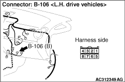
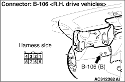
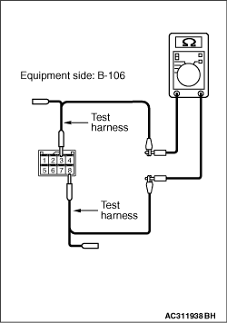
(1)Remove the electric power steering-ECU, and measure at the equipment side.
|
|
(2)Resistance at B-106 electric power steering-ECU connector terminal Nos.3 and 8
OK: 1 kΩ or more
Q.
Is the check result normal?
<1 kΩ or more> It is determined that there is an intermittent malfunction such as poor engaged connector(s) or open circuit (Refer to GROUP 00, How to Cope with Intermittent Malfunction ).
<Less than 1 kΩ> Replace the electric power steering-ECU.
|
|
| caution |
The strand end of the twist wire should be within 10 cm from the connector. For details refer to .
|
Q.
Is the check result normal?
Go to Step 32.
Repair the defective connector.
|
|
(1)Disconnect the joint connector (CAN2) and the G and yaw rate sensor connector, and measure at the wiring harness side.
(2)Ignition switch: OFF (LOCK)
(3)
| caution |
When measuring the resistance, disconnect the negative battery terminal. For details refer to .
|
Ensure that the negative battery terminal is disconnected.
|
|
(4)Continuity between B-107 joint connector (CAN2) terminal Nos.8 and 19
OK: More than 2 Ω
| caution |
Strictly observe the specified wiring harness repair procedure. For details refer to .
|
Q.
Is the check result normal?
<More than 2 Ω> Go to Step 33.
<2 Ω or less> Repair the wiring harness between joint connector (CAN2) and the TCL/ASC-ECU connector.
|
|
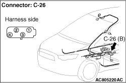
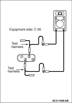
(1)Remove the G and yaw rate sensor, and measure at the equipment side.
|
|
(2)Resistance at C-26 G and yaw rate sensor connector terminal Nos.2 and 3
OK: 1 kΩ or more
Q.
Is the check result normal?
<1 kΩ or more> It is determined that there is an intermittent malfunction such as poor engaged connector(s) or open circuit (Refer to GROUP 00, How to Cope with Intermittent Malfunction ).
<Less than 1 kΩ> Replace the electric power steering-ECU.
|
|
(1)Disconnect the joint connector (CAN2) and the intermediate connector, and measure at the wiring harness side.
(2)Ignition switch: OFF (LOCK)
(3)
| caution |
When measuring the resistance, disconnect the negative battery terminal. For details refer to .
|
Ensure that the negative battery terminal is disconnected.
|
|
(4)Measure the continuity between B-107 joint connector (CAN2) terminal Nos.9 and 20.
OK: More than 2 Ω
| caution |
Strictly observe the specified wiring harness repair procedure. For details refer to .
|
Q.
Is the check result normal?
<More than 2 Ω> It is determined that there is an intermittent malfunction such as poor engaged connector(s) or open circuit (Refer to GROUP 00, How to Cope with Intermittent Malfunction ).
<2 Ω or less> Repair the wiring harness between joint connector (CAN2) and the intermediate connector.
|
)
)
)
)
)
)
)
)
)
)
)
)
)
)
)
)
)
)
)
)
)
)
)
)
)
)
)
)
)
)
)
)
)
)
)
)
)
)
)
)
)
)
)
)
)
)
)
)
)
)
)
)
)