|
| caution |
The strand end of the twist wire should be within 10 cm from the connector. For details refer to  . .
|
Q.
Are the check results normal?
 Go to Step 2. Go to Step 2.
 Repair the defective connector. Repair the defective connector.
|
|
(1)Disconnect the engine-ECU <M/T> or engine-A-M/T-ECU <Automated manual transmission> connector and the combination meter connector, and measure at the wiring harness side.
(2)Connect the negative battery terminal, and turn the ignition switch to the ON position.
|
|
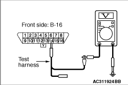
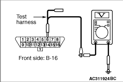
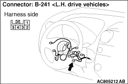
(3)Voltage between B-16 diagnosis connector terminal No.14 and body earth
OK: 4.0 V or less
|
|
(4)Voltage between B-16 diagnosis connector terminal No.6 and body earth
OK: 4.0 V or less
(5)Disconnect the negative battery terminal.
Q.
Are the check results normal?
YES <all of the measurement results show 4.0 V or less> : It is determined that there is an intermittent malfunction such as poor engaged connector(s) or open circuit (Refer to GROUP 00, How to Cope with Intermittent Malfunction ).
NO <The voltage between terminal No.14 and body earth is more than 4.0 V> : Go to Step 3. : Go to Step 3.
NO <The voltage between terminal No.6 and body earth is more than 4.0 V> : Go to Step 28.
|
|
| caution |
The strand end of the twist wire should be within 10 cm from the connector. For details refer to .
|
Q.
Is the check result normal?
Go to Step 4.
Repair the defective connector.
|
|
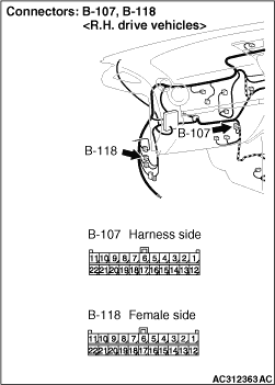
(1)Disconnect the connector, and measure at its female-side intermediate connector (at the front wiring harness side).
(2)Connect the negative battery terminal, and turn the ignition switch to the ON position.
|
|
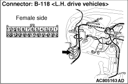
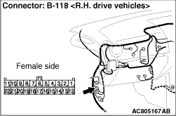
(3)Voltage between B-118 intermediate connector terminal No.12 and body earth
OK: 4.0 V or less
Q.
Is the check result normal?
<4.0 V or less> Go to Step 5.
<more than 4.0 V> Go to Step 18.
|
|
| caution |
The strand end of the twist wire should be within 10 cm from the connector. For details refer to .
|
|
|
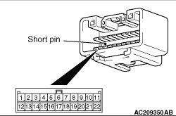
When checking the joint connector, ensure that its wiring harness side and its short pins are not damaged.
Q.
Is the check result normal?
Go to Step 6.
Repair a defective connector or replace the joint connector.
|
|
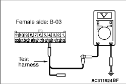
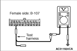
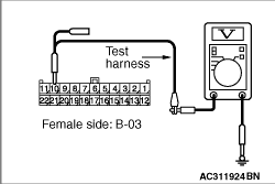
(1)Disconnect the connector, and measure at the wiring harness side.
(2)Connect the negative battery terminal, and turn the ignition switch to the ON position.
|
|
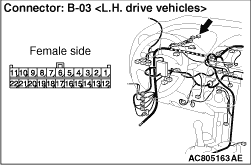
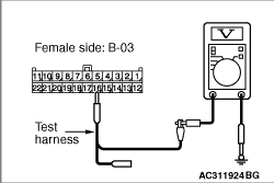
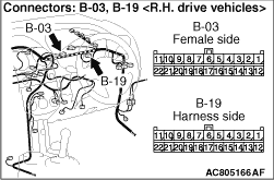
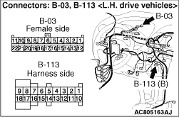
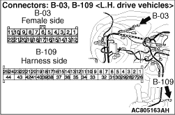
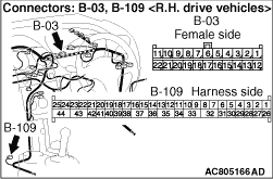
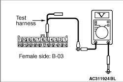
(3)Voltage between B-03 joint connector (CAN1) terminal No.15 and body earth
OK: 4.0 V or less
|
|
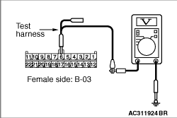
(4)Voltage between B-03 joint connector (CAN1) terminal No.16 and body earth
OK: 4.0 V or less
|

|
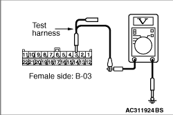
(5)Voltage between B-03 joint connector (CAN1) terminal No.17 and body earth <L.H. drive vehicles>
OK: 4.0 V or less
|
|
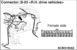
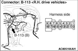
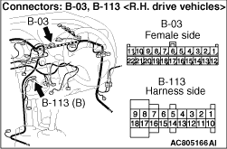
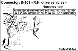
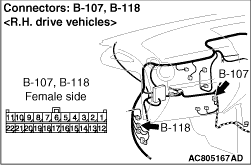
(6)Voltage between B-03 joint connector (CAN1) terminal No.14 and body earth <R.H. drive vehicles>
OK: 4.0 V or less
|

|
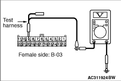
(7)Voltage between B-03 joint connector (CAN1) terminal No.18 and body earth
OK: 4.0 V or less
|

|
(8)Voltage between B-03 joint connector (CAN1) terminal No.20 and body earth
OK: 4.0 V or less
|
|
(9)Voltage between B-03 joint connector (CAN1) terminal No.21 and body earth
OK: 4.0 V or less
(10)Disconnect the negative battery terminal.
Q.
Are the check results normal?
YES <all of the measurement results show 4.0 V or less> : Go to Step 17.
NO <The voltage between terminal No.15 and body earth is more than 4.0 V> : Go to Step 7.
NO <The voltage between terminal No.16 and body earth is more than 4.0 V> : Go to Step 8.
NO <The voltage between terminal No.17 and body earth is more than 4.0 V> : Go to Step 10.
NO <The voltage between terminal No.14 and body earth is more than 4.0 V> : Go to Step 10.
NO <The voltage between terminal No.18 and body earth is more than 4.0 V> : Go to Step 12.
NO <The voltage between terminal No.20 and body earth is more than 4.0 V> : Go to Step 14.
NO <The voltage between terminal No.21 and body earth is more than 4.0 V> : Go to Step 16.
|
|
(1)Disconnect the joint connector (CAN1) and the combination meter connector, and measure at the wiring harness side.
(2)Connect the negative battery terminal, and turn the ignition switch to the ON position.
|
|
(3)Voltage between B-03 joint connector (CAN1) terminal No.15 and body earth
OK: Less than 1.0 V
(4)Disconnect the negative battery terminal.
| caution |
Strictly observe the specified wiring harness repair procedure. For details refer to .
|
Q.
Is the check result normal?
<less than 1.0 V> It is determined that there is an intermittent malfunction such as poor engaged connector(s) or open circuit (Refer to GROUP 00, How to Cope with Intermittent Malfunction ).
<1.0 V or more> Repair the wiring harness between joint connector (CAN1) and the combination meter connector.
|
|
| caution |
The strand end of the twist wire should be within 10 cm from the connector. For details refer to .
|
Q.
Is the check result normal?
Go to Step 9.
Repair the defective connector.
|
|
(1)Disconnect the joint connector (CAN1) and the ETACS-ECU connector, and measure at the wiring harness side.
(2)Connect the negative battery terminal, and turn the ignition switch to the ON position.
|
|
(3)Voltage between B-03 joint connector (CAN1) terminal No.16 and body earth
OK: Less than 1.0 V
(4)Disconnect the negative battery terminal.
| caution |
Strictly observe the specified wiring harness repair procedure. For details refer to .
|
Q.
Is the check result normal?
<less than 1.0 V> It is determined that there is an intermittent malfunction such as poor engaged connector(s) or open circuit (Refer to GROUP 00, How to Cope with Intermittent Malfunction ).
<1.0 V or more> Repair the wiring harness between the joint connector (CAN1) and the ETACS-ECU connector.
|
|
| caution |
The strand end of the twist wire should be within 10 cm from the connector. For details refer to .
|
Q.
Is the check result normal?
Go to Step 11.
Repair the defective connector.
|
|
(1)Disconnect the joint connector (CAN1) and the A/C-ECU connector, and measure at the wiring harness side.
(2)Connect the negative battery terminal, and turn the ignition switch to the ON position.
|
|
(3)Voltage between B-03 joint connector (CAN1) terminal No.17 and body earth <L.H. drive vehicles>
OK: Less than 1.0 V
|
|
(4)Voltage between B-03 joint connector (CAN1) terminal No.14 and body earth <R.H. drive vehicles>
OK: Less than 1.0 V
(5)Disconnect the negative battery terminal.
| caution |
Strictly observe the specified wiring harness repair procedure. For details refer to .
|
Q.
Is the check result normal?
<less than 1.0 V> It is determined that there is an intermittent malfunction such as poor engaged connector(s) or open circuit (Refer to GROUP 00, How to Cope with Intermittent Malfunction ).
<1.0 V or more> Repair the wiring harness between the joint connector (CAN1) and the A/C-ECU connector.
|
|
| caution |
The strand end of the twist wire should be within 10 cm from the connector. For details refer to .
|
Q.
Is the check result normal?
Go to Step 13.
Repair the defective connector.
|
|
(1)Disconnect the joint connector (CAN1) and the SRS-ECU connector, and measure at the wiring harness side.
(2)Connect the negative battery terminal, and turn the ignition switch to the ON position.
|
|
(3)Voltage between B-03 joint connector (CAN1) terminal No.18 and body earth
OK: Less than 1.0 V
(4)Disconnect the negative battery terminal.
| caution |
Strictly observe the specified wiring harness repair procedure. For details refer to .
|
Q.
Is the check result normal?
<less than 1.0 V> It is determined that there is an intermittent malfunction such as poor engaged connector(s) or open circuit (Refer to GROUP 00, How to Cope with Intermittent Malfunction ).
<1.0 V or more> Repair the wiring harness between the joint connector (CAN1) and the SRS-ECU connector.
|

|
| caution |
The strand end of the twist wire should be within 10 cm from the connector. For details refer to .
|
Q.
Is the check result normal?
Go to Step 15.
Repair the defective connector.
|
|
(1)Disconnect the joint connector (CAN1) and the steering wheel sensor connector, and measure at the wiring harness side.
(2)Connect the negative battery terminal, and turn the ignition switch to the ON position.
|
|
(3)Voltage between B-03 joint connector (CAN1) terminal No.20 and body earth
OK: Less than 1.0 V
(4)Disconnect the negative battery terminal.
| caution |
Strictly observe the specified wiring harness repair procedure. For details refer to .
|
Q.
Is the check result normal?
<less than 1.0 V> It is determined that there is an intermittent malfunction such as poor engaged connector(s) or open circuit (Refer to GROUP 00, How to Cope with Intermittent Malfunction ).
<1.0 V or more> Repair the wiring harness between the joint connector (CAN1) and the steering wheel sensor connector.
|
|
(1)Disconnect the connector, and measure at the wiring harness side.
(2)Connect the negative battery terminal, and turn the ignition switch to the ON position.
|
|
(3)Voltage between B-03 joint connector (CAN1) terminal No.21 and body earth
OK: Less than 1.0 V
(4)Disconnect the negative battery terminal.
| caution |
Strictly observe the specified wiring harness repair procedure. For details refer to .
|
Q.
Is the check result normal?
<less than 1.0 V> It is determined that there is an intermittent malfunction such as poor engaged connector(s) or open circuit (Refer to GROUP 00, How to Cope with Intermittent Malfunction ).
<1.0 V or more> Repair the wiring harness between the joint connector (CAN1) and the diagnosis connector.
|
|
(1)Disconnect the connector, and measure at the wiring harness side.
(2)Connect the negative battery terminal, and turn the ignition switch to the ON position.
|

|
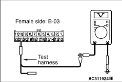
(3)Voltage between B-03 joint connector (CAN1) terminal No.22 and body earth
OK: Less than 1.0 V
(4)Disconnect the negative battery terminal.
| caution |
Strictly observe the specified wiring harness repair procedure. For details refer to .
|
Q.
Is the check result normal?
<less than 1.0 V> It is determined that there is an intermittent malfunction such as poor engaged connector(s) or open circuit (Refer to GROUP 00, How to Cope with Intermittent Malfunction ).
<1.0 V or more> Repair the wiring harness between the joint connector (CAN1) and the intermediate connector.
|
|
| caution |
The strand end of the twist wire should be within 10 cm from the connector. For details refer to .
|
When checking the joint connector, ensure that its wiring harness side is not damaged.
Q.
Is the check result normal?
Go to Step 19.
Repair a defective connector or replace the joint connector (front wiring harness assembly).
|
|
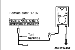
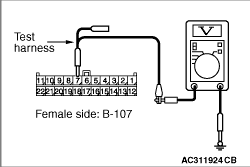
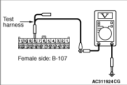
(1)Disconnect the connector, and measure at the wiring harness side.
(2)Connect the negative battery terminal, and turn the ignition switch to the ON position.
|
|
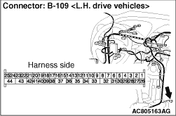
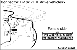
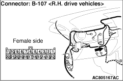
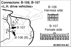
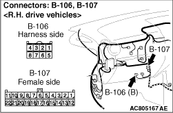
(3)Voltage between B-107 joint connector (CAN2) terminal No.18 and body earth
OK: 4.0 V or less
|
|
(4)Voltage between B-107 joint connector (CAN2) terminal No.22 and body earth
OK: 4.0 V or less
|

|
(5)Voltage between B-107 joint connector (CAN2) terminal No.21 and body earth
OK: 4.0 V or less
|
|
(6)Voltage between B-107 joint connector (CAN2) terminal No.19 and body earth
OK: 4.0 V or less
(7)Disconnect the negative battery terminal.
Q.
Are the check results normal?
YES <all of the measurement results show 4.0 V or less> : Go to Step 27.
NO <The voltage between terminal No.18 and body earth is more than 4.0 V> : Go to Step 20.
NO <The voltage between terminal No.22 and body earth is more than 4.0 V> : Go to Step 21.
NO <The voltage between terminal No.21 and body earth is more than 4.0 V> : Go to Step 23.
NO <The voltage between terminal No.19 and body earth is more than 4.0 V> : Go to Step 25.
|
|
(1)Disconnect the engine-ECU <M/T> or engine-A-M/T-ECU <Automated manual transmission> connector and the joint connector (CAN2), and measure at the wiring harness side.
(2)Connect the negative battery terminal, and turn the ignition switch to the ON position.
|
|
(3)Voltage between B-107 joint connector (CAN1) terminal No.18 and body earth
OK: Less than 1.0 V
(4)Disconnect the negative battery terminal.
| caution |
Strictly observe the specified wiring harness repair procedure. For details refer to .
|
Q.
Is the check result normal?
<less than 1.0 V> It is determined that there is an intermittent malfunction such as poor engaged connector(s) or open circuit (Refer to GROUP 00, How to Cope with Intermittent Malfunction ).
<1.0 V or more> Repair the wiring harness between the intermediate connector and the engine-ECU <M/T> or engine-A-M/T-ECU <Automated manual transmission> connector.
|
|
| caution |
The strand end of the twist wire should be within 10 cm from the connector. For details refer to .
|
Q.
Is the check result normal?
Go to Step 22.
Repair the defective connector.
|
|
(1)Disconnect the joint connector (CAN2) and the TCL/ASC-ECU connector, and measure at the wiring harness side.
(2)Connect the negative battery terminal, and turn the ignition switch to the ON position.
|
|
(3)Voltage between B-107 joint connector (CAN2) terminal No.22 and body earth
OK: Less than 1.0 V
(4)Disconnect the negative battery terminal.
| caution |
Strictly observe the specified wiring harness repair procedure. For details refer to .
|
Q.
Is the check result normal?
<less than 1.0 V> It is determined that there is an intermittent malfunction such as poor engaged connector(s) or open circuit (Refer to GROUP 00, How to Cope with Intermittent Malfunction ).
<1.0 V or more> Repair the wiring harness between the joint connector (CAN2) and the TCL/ASC-ECU connector.
|
|
| caution |
The strand end of the twist wire should be within 10 cm from the connector. For details refer to .
|
Q.
Is the check result normal?
Go to Step 24.
Repair the defective connector.
|
|
(1)Disconnect the joint connector (CAN2) and the electric power steering-ECU connector, and measure at the wiring harness side.
(2)Connect the negative battery terminal, and turn the ignition switch to the ON position.
|
|
(3)Voltage between B-107 joint connector (CAN2) terminal No.21 and body earth
OK: Less than 1.0 V
(4)Disconnect the negative battery terminal.
| caution |
Strictly observe the specified wiring harness repair procedure. For details refer to .
|
Q.
Is the check result normal?
<less than 1.0 V> It is determined that there is an intermittent malfunction such as poor engaged connector(s) or open circuit (Refer to GROUP 00, How to Cope with Intermittent Malfunction ).
<1.0 V or more> Repair the wiring harness between the joint connector (CAN2) and the electric power steering-ECU connector.
|
|
| caution |
The strand end of the twist wire should be within 10 cm from the connector. For details refer to .
|
Q.
Is the check result normal?
Go to Step 26.
Repair the defective connector.
|
|
(1)Disconnect the joint connector (CAN2) and the G and yaw rate sensor connector, and measure at the wiring harness side.
(2)Connect the negative battery terminal, and turn the ignition switch to the ON position.
|
|
(3)Voltage between B-107 joint connector (CAN2) terminal No.19 and body earth
OK: Less than 1.0 V
(4)Disconnect the negative battery terminal.
| caution |
Strictly observe the specified wiring harness repair procedure. For details refer to .
|
Q.
Is the check result normal?
<less than 1.0 V> It is determined that there is an intermittent malfunction such as poor engaged connector(s) or open circuit (Refer to GROUP 00, How to Cope with Intermittent Malfunction ).
<1.0 V or more> Repair the wiring harness between the joint connector (CAN2) and the G and yaw rate sensor connector.
|
|
(1)Disconnect the joint connector (CAN2) and the intermediate connector, and measure at the wiring harness side.
(2)Connect the negative battery terminal, and turn the ignition switch to the ON position.
|
|
(3)Voltage between B-107 joint connector (CAN2) terminal No.20 and body earth
OK: Less than 1.0 V
(4)Disconnect the negative battery terminal.
| caution |
Strictly observe the specified wiring harness repair procedure. For details refer to .
|
Q.
Is the check result normal?
<less than 1.0 V> It is determined that there is an intermittent malfunction such as poor engaged connector(s) or open circuit (Refer to GROUP 00, How to Cope with Intermittent Malfunction ).
<1.0 V or more> Repair the wiring harness between the joint connector (CAN2) and the intermediate connector.
|
|
| caution |
The strand end of the twist wire should be within 10 cm from the connector. For details refer to .
|
Q.
Is the check result normal?
Go to Step 29.
Repair the defective connector.
|
|
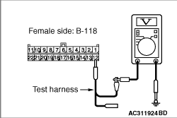
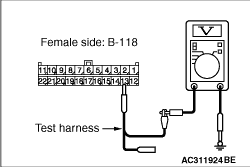
(1)Disconnect the connector, and measure at its female-side intermediate connector (at the front wiring harness side).
(2)Connect the negative battery terminal, and turn the ignition switch to the ON position.
|
|
(3)Voltage between B-118 intermediate connector terminal No.13 and body earth
OK: 4.0 V or less
Q.
Is the check result normal?
<4.0 V or less> Go to Step 30.
<more than 4.0 V> Go to Step 43.
|
|
| caution |
The strand end of the twist wire should be within 10 cm from the connector. For details refer to .
|
|
|
When checking the joint connector, ensure that its wiring harness side and its short pins are not damaged.
Q.
Is the check result normal?
Go to Step 31.
Repair a defective connector or replace the joint connector.
|
|
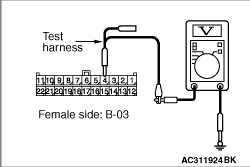
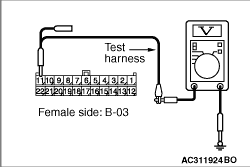
(1)Disconnect the connector, and measure at the wiring harness side.
(2)Connect the negative battery terminal, and turn the ignition switch to the ON position.
|
|
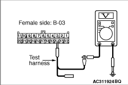
(3)Voltage between B-03 joint connector (CAN1) terminal No.4 and body earth
OK: 4.0 V or less
|
|
(4)Voltage between B-03 joint connector (CAN1) terminal No.5 and body earth
OK: 4.0 V or less
|
|
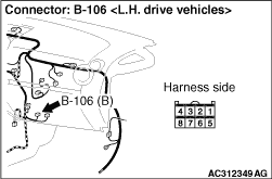
(5)Voltage between B-03 joint connector (CAN1) terminal No.6 and body earth <L.H. drive vehicles>
OK: 4.0 V or less
|
|
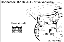
(6)Voltage between B-03 joint connector (CAN1) terminal No.3 and body earth <R.H. drive vehicles>
OK: 4.0 V or less
|

|
(7)Voltage between B-03 joint connector (CAN1) terminal No.7 and body earth
OK: 4.0 V or less
|
|
(8)Voltage between B-03 joint connector (CAN1) terminal No.9 and body earth
OK: 4.0 V or less
|
|
(9)Voltage between B-03 joint connector (CAN1) terminal No.10 and body earth
OK: 4.0 V or less
(10)Disconnect the negative battery terminal.
Q.
Are the check results normal?
YES <all of the measurement results show 4.0 V or less> : Go to Step 42.
NO <The voltage between terminal No.4 and body earth is more than 4.0 V> : Go to Step 32.
NO <The voltage between terminal No.5 and body earth is more than 4.0 V> : Go to Step 33.
NO <The voltage between terminal No.6 and body earth is more than 4.0 V> : Go to Step 35.
NO <The voltage between terminal No.3 and body earth is more than 4.0 V> : Go to Step 35.
NO <The voltage between terminal No.7 and body earth is more than 4.0 V> : Go to Step 37.
NO <The voltage between terminal No.9 and body earth is more than 4.0 V> : Go to Step 39.
NO <The voltage between terminal No.10 and body earth is more than 4.0 V> : Go to Step 41.
|
|
(1)Disconnect the joint connector (CAN1) and the combination meter connector, and measure at the wiring harness side.
(2)Connect the negative battery terminal, and turn the ignition switch to the ON position.
|
|
(3)Voltage between B-03 joint connector (CAN1) terminal No.4 and body earth
OK: Less than 1.0 V
(4)Disconnect the negative battery terminal.
| caution |
Strictly observe the specified wiring harness repair procedure. For details refer to .
|
Q.
Is the check result normal?
<less than 1.0 V> It is determined that there is an intermittent malfunction such as poor engaged connector(s) or open circuit (Refer to GROUP 00, How to Cope with Intermittent Malfunction ).
<1.0 V or more> Repair the wiring harness between joint connector (CAN1) and the combination meter connector.
|
|
| caution |
The strand end of the twist wire should be within 10 cm from the connector. For details refer to .
|
Q.
Is the check result normal?
Go to Step 34.
Repair the defective connector.
|
|
(1)Disconnect the joint connector (CAN1) and the ETACS-ECU connector, and measure at the wiring harness side.
(2)Connect the negative battery terminal, and turn the ignition switch to the ON position.
|
|
(3)Voltage between B-03 joint connector (CAN1) terminal No.5 and body earth
OK: Less than 1.0 V
(4)Disconnect the negative battery terminal.
| caution |
Strictly observe the specified wiring harness repair procedure. For details refer to .
|
Q.
Is the check result normal?
<less than 1.0 V> It is determined that there is an intermittent malfunction such as poor engaged connector(s) or open circuit (Refer to GROUP 00, How to Cope with Intermittent Malfunction ).
<1.0 V or more> Repair the wiring harness between the joint connector (CAN1) and the ETACS-ECU connector.
|
|
| caution |
The strand end of the twist wire should be within 10 cm from the connector. For details refer to .
|
Q.
Is the check result normal?
Go to Step 36.
Repair the defective connector.
|
|
(1)Disconnect the joint connector (CAN1) and the A/C-ECU connector, and measure at the wiring harness side.
(2)Connect the negative battery terminal, and turn the ignition switch to the ON position.
|
|
(3)Voltage between B-03 joint connector (CAN1) terminal No.6 and body earth <L.H. drive vehicles>
OK: Less than 1.0 V
|
|
(4)Voltage between B-03 joint connector (CAN1) terminal No.3 and body earth <R.H. drive vehicles>
OK: Less than 1.0 V
(5)Disconnect the negative battery terminal.
| caution |
Strictly observe the specified wiring harness repair procedure. For details refer to .
|
Q.
Is the check result normal?
<less than 1.0 V> It is determined that there is an intermittent malfunction such as poor engaged connector(s) or open circuit (Refer to GROUP 00, How to Cope with Intermittent Malfunction ).
<1.0 V or more> Repair the wiring harness between the joint connector (CAN1) and the A/C-ECU connector.
|
|
| caution |
The strand end of the twist wire should be within 10 cm from the connector. For details refer to .
|
Q.
Is the check result normal?
Go to Step 38.
Repair the defective connector.
|
|
(1)Disconnect the joint connector (CAN1) and the SRS-ECU connector, and measure at the wiring harness side.
(2)Connect the negative battery terminal, and turn the ignition switch to the ON position.
|
|
(3)Voltage between B-03 joint connector (CAN1) terminal No.7 and body earth
OK: Less than 1.0 V
(4)Disconnect the negative battery terminal.
| caution |
Strictly observe the specified wiring harness repair procedure. For details refer to .
|
Q.
Is the check result normal?
<less than 1.0 V> It is determined that there is an intermittent malfunction such as poor engaged connector(s) or open circuit (Refer to GROUP 00, How to Cope with Intermittent Malfunction ).
<1.0 V or more> Repair the wiring harness between the joint connector (CAN1) and the SRS-ECU connector.
|
|
| caution |
The strand end of the twist wire should be within 10 cm from the connector. For details refer to .
|
Q.
Is the check result normal?
Go to Step 40.
Repair the defective connector.
|
|
(1)Disconnect the joint connector (CAN1) and the steering wheel sensor connector, and measure at the wiring harness side.
(2)Connect the negative battery terminal, and turn the ignition switch to the ON position.
|
|
(3)Voltage between B-03 joint connector (CAN1) terminal No.9 and body earth
OK: Less than 1.0 V
(4)Disconnect the negative battery terminal.
| caution |
Strictly observe the specified wiring harness repair procedure. For details refer to .
|
Q.
Is the check result normal?
<less than 1.0 V> It is determined that there is an intermittent malfunction such as poor engaged connector(s) or open circuit (Refer to GROUP 00, How to Cope with Intermittent Malfunction ).
<1.0 V or more> Repair the wiring harness between the joint connector (CAN1) and the steering wheel sensor connector.
|
|
(1)Disconnect the connector, and measure at the wiring harness side.
(2)Connect the negative battery terminal, and turn the ignition switch to the ON position.
|
|
(3)Voltage between B-03 joint connector (CAN1) terminal No.10 and body earth
OK: Less than 1.0 V
(4)Disconnect the negative battery terminal.
| caution |
Strictly observe the specified wiring harness repair procedure. For details refer to .
|
Q.
Is the check result normal?
<less than 1.0 V> It is determined that there is an intermittent malfunction such as poor engaged connector(s) or open circuit (Refer to GROUP 00, How to Cope with Intermittent Malfunction ).
<1.0 V or more> Repair the wiring harness between the joint connector (CAN1) and the diagnosis connector.
|
|
(1)Disconnect the connector, and measure at the wiring harness side.
(2)Connect the negative battery terminal, and turn the ignition switch to the ON position.
|
|
(3)Voltage between B-03 joint connector (CAN1) terminal No.11 and body earth
OK: Less than 1.0 V
(4)Disconnect the negative battery terminal.
| caution |
Strictly observe the specified wiring harness repair procedure. For details refer to .
|
Q.
Is the check result normal?
<less than 1.0 V> It is determined that there is an intermittent malfunction such as poor engaged connector(s) or open circuit (Refer to GROUP 00, How to Cope with Intermittent Malfunction ).
<1.0 V or more> Repair the wiring harness between the joint connector (CAN1) and the intermediate connector.
|
|
| caution |
The strand end of the twist wire should be within 10 cm from the connector. For details refer to .
|
When checking the joint connector, ensure that its wiring harness side is not damaged.
Q.
Is the check result normal?
Go to Step 44.
Repair a defective connector or replace the joint connector (front wiring harness assembly).
|
|
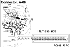
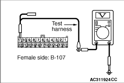
(1)Disconnect the connector, and measure at the wiring harness side.
(2)Connect the negative battery terminal, and turn the ignition switch to the ON position.
|
|
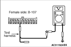
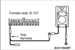
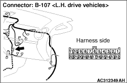
(3)Voltage between B-107 joint connector (CAN2) terminal No.7 and body earth
OK: 4.0 V or less
|
|
(4)Voltage between B-107 joint connector (CAN2) terminal No.11 and body earth
OK: 4.0 V or less
|
|
(5)Voltage between B-107 joint connector (CAN2) terminal No.10 and body earth
OK: 4.0 V or less
|
|
(6)Voltage between B-107 joint connector (CAN2) terminal No.8 and body earth
OK: 4.0 V or less
(7)Disconnect the negative battery terminal.
Q.
Are the check results normal?
YES <all of the measurement results show 4.0 V or less> : Go to Step 52.
NO <The voltage between terminal No.7 and body earth is more than 4.0 V> : Go to Step 45.
NO <The voltage between terminal No.11 and body earth is more than 4.0 V> : Go to Step 46.
NO <The voltage between terminal No.10 and body earth is more than 4.0 V> : Go to Step 48.
NO <The voltage between terminal No.8 and body earth is more than 4.0 V> : Go to Step 50.
|
|
(1)Disconnect the engine-ECU <M/T> or engine-A-M/T-ECU <Automated manual transmission> connector and the joint connector (CAN2), and measure at the wiring harness side.
(2)Connect the negative battery terminal, and turn the ignition switch to the ON position.
|
|
(3)Voltage between B-107 joint connector (CAN1) terminal No.7 and body earth
OK: Less than 1.0 V
(4)Disconnect the negative battery terminal.
| caution |
Strictly observe the specified wiring harness repair procedure. For details refer to .
|
Q.
Is the check result normal?
<less than 1.0 V> It is determined that there is an intermittent malfunction such as poor engaged connector(s) or open circuit (Refer to GROUP 00, How to Cope with Intermittent Malfunction ).
<1.0 V or more> Repair the wiring harness between the intermediate connector and the engine-ECU <M/T> or engine-A-M/T-ECU <Automated manual transmission> connector.
|
|
| caution |
The strand end of the twist wire should be within 10 cm from the connector. For details refer to .
|
Q.
Is the check result normal?
Go to Step 47.
Repair the defective connector.
|
|
(1)Disconnect the joint connector (CAN2) and the TCL/ASC-ECU connector, and measure at the wiring harness side.
(2)Connect the negative battery terminal, and turn the ignition switch to the ON position.
|
|
(3)Voltage between B-107 joint connector (CAN2) terminal No.11 and body earth
OK: Less than 1.0 V
(4)Disconnect the negative battery terminal.
| caution |
Strictly observe the specified wiring harness repair procedure. For details refer to .
|
Q.
Is the check result normal?
<less than 1.0 V> It is determined that there is an intermittent malfunction such as poor engaged connector(s) or open circuit (Refer to GROUP 00, How to Cope with Intermittent Malfunction ).
<1.0 V or more> Repair the wiring harness between the joint connector (CAN2) and the TCL/ASC-ECU connector.
|
|
| caution |
The strand end of the twist wire should be within 10 cm from the connector. For details refer to .
|
Q.
Is the check result normal?
Go to Step 49.
Repair the defective connector.
|
|
(1)Disconnect the joint connector (CAN2) and the electric power steering-ECU connector, and measure at the wiring harness side.
(2)Connect the negative battery terminal, and turn the ignition switch to the ON position.
|
|
(3)Voltage between B-107 joint connector (CAN2) terminal No.10 and body earth
OK: Less than 1.0 V
(4)Disconnect the negative battery terminal.
| caution |
Strictly observe the specified wiring harness repair procedure. For details refer to .
|
Q.
Is the check result normal?
<less than 1.0 V> It is determined that there is an intermittent malfunction such as poor engaged connector(s) or open circuit (Refer to GROUP 00, How to Cope with Intermittent Malfunction ).
<1.0 V or more> Repair the wiring harness between the joint connector (CAN2) and the electric power steering-ECU connector.
|
|
| caution |
The strand end of the twist wire should be within 10 cm from the connector. For details refer to .
|
Q.
Is the check result normal?
Go to Step 51.
Repair the defective connector.
|
|
(1)Disconnect the joint connector (CAN2) and the G and yaw rate sensor connector, and measure at the wiring harness side.
(2)Connect the negative battery terminal, and turn the ignition switch to the ON position.
|
|
(3)Voltage between B-107 joint connector (CAN2) terminal No.8 and body earth
OK: Less than 1.0 V
(4)Disconnect the negative battery terminal.
| caution |
Strictly observe the specified wiring harness repair procedure. For details refer to .
|
Q.
Is the check result normal?
<less than 1.0 V> It is determined that there is an intermittent malfunction such as poor engaged connector(s) or open circuit (Refer to GROUP 00, How to Cope with Intermittent Malfunction ).
<1.0 V or more> Repair the wiring harness between the joint connector (CAN2) and the G and yaw rate sensor connector.
|
|
(1)Disconnect the joint connector (CAN2) and the intermediate connector, and measure at the wiring harness side.
(2)Connect the negative battery terminal, and turn the ignition switch to the ON position.
|

|
(3)Voltage between B-107 joint connector (CAN2) terminal No.9 and body earth
OK: Less than 1.0 V
(4)Disconnect the negative battery terminal.
| caution |
Strictly observe the specified wiring harness repair procedure. For details refer to .
|
Q.
Is the check result normal?
<less than 1.0 V> It is determined that there is an intermittent malfunction such as poor engaged connector(s) or open circuit (Refer to GROUP 00, How to Cope with Intermittent Malfunction ).
<1.0 V or more> Repair the wiring harness between the joint connector (CAN2) and the intermediate connector.
|
)
)
)
)
)
)
)
)
)
)
)
)
)
)
)
)
)
)
)
)
)
)
)
)
)
)
)
)
)
)
)
)
)
)
)
)
)
)
)
)
)
)
)
)
)
)
)
)
)
)
)
)
)
)
)
)
)
)
)
)
)
)
)
)