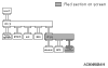
M.U.T.-III SCREEN
|
DIAGNOSIS DETAILS
|
REFERENCE PAGE
|
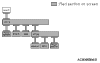
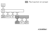
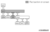
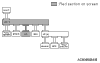
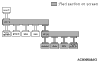
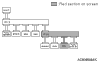
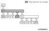
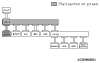
<Comment>
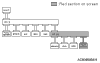
Short circuit to battery in red displayed area is estimated.
|
Diagnosis Item 1
Diagnose the CAN bus lines for short to power supply <Vehicles without A/C and TCL/ASC system>
|

|
<Comment>
Grounding in red displayed area is estimated.
|
Diagnosis Item 5
Diagnose the CAN bus lines for short to earth <Vehicles without A/C and TCL/ASC system>
|
|
<Comment>
Short circuit between CAN_H and CAN_L in red displayed area is estimated.
|
Diagnosis Item 9
Diagnose the lines between CAN_L and CAN_H for short circuit <Vehicles without A/C and TCL/ASC system>
|
|
<Comment>
Mulfunction of terminating resistance is estimated.
|
Diagnosis Item 13
The terminators resistors at both ends or terminator resistor at one side may be defective
|
|
<Comment>
Disconnection in red displayed area is estimated.
|
Diagnosis Item 14
Diagnose the lines between the joint connectors (CAN1 and CAN2)
|
|
<Comment>
Disconnection in red displayed area is estimated.
|
Diagnosis Item 15
Diagnose the lines from the main bus line to the engine-ECU <M/T> or engine-A-M/T-ECU <Automated manual transmission>.
|
|
<Comment>
Disconnection in red displayed area is estimated.
|
Diagnosis Item 16
Diagnose the lines from the main bus line to the ABS-ECU <Vehicles without TCL/ASC system>
|
|
<Comment>
Disconnection in red displayed area is estimated.
|
Diagnosis Item 19
Diagnose the lines from the main bus line to the electric power steering-ECU
|
|
<Comment>
Disconnection in red displayed area is estimated.
|
Diagnosis Item 20
Diagnose the lines from the main bus line to the combination meter
|
|
<Comment>
Disconnection in red displayed area is estimated.
|
Diagnosis Item 21
Diagnose the lines from the main bus line to the ETACS-ECU
|
|
<Comment>
Disconnection in red displayed area is estimated.
|
Diagnosis Item 23
Diagnose the lines from the main bus line to the SRS-ECU
|
|
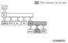
M.U.T.-III SCREEN
|
DIAGNOSIS DETAILS
|
REFERENCE PAGE
|
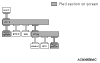
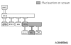
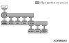
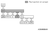
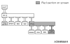
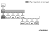
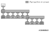
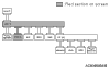
<Comment>
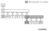
Short circuit to battery in red displayed area is estimated.
|
Diagnosis Item 2
Diagnose the CAN bus lines for short to power supply <Vehicles with A/C and without TCL/ASC system>
|
|
<Comment>
Grounding in red displayed area is estimated.
|
Diagnosis Item 6
Diagnose the CAN bus lines for short to earth <Vehicles with A/C and without TCL/ASC system>
|
|
<Comment>
Short circuit between CAN_H and CAN_L in red displayed area is estimated.
|
Diagnosis Item 10
Diagnose the lines between CAN_L and CAN_H for short circuit <Vehicles with A/C and without TCL/ASC system>
|
|
<Comment>
Mulfunction of terminating resistance is estimated.
|
Diagnosis Item 13
The terminators resistors at both ends or terminator resistor at one side may be defective
|
|
<Comment>
Disconnection in red displayed area is estimated.
|
Diagnosis Item 14
Diagnose the lines between the joint connectors (CAN1 and CAN2)
|
|
<Comment>
Disconnection in red displayed area is estimated.
|
Diagnosis Item 15
Diagnose the lines from the main bus line to the engine-ECU <M/T> or engine-A-M/T-ECU <Automated manual transmission>.
|
|
<Comment>
Disconnection in red displayed area is estimated.

|
Diagnosis Item 16
Diagnose the lines from the main bus line to the ABS-ECU <Vehicles without TCL/ASC system>
|
|
<Comment>
Disconnection in red displayed area is estimated.
|
Diagnosis Item 19
Diagnose the lines from the main bus line to the electric power steering-ECU
|
|
<Comment>
Disconnection in red displayed area is estimated.
|
Diagnosis Item 20
Diagnose the lines from the main bus line to the combination meter
|
|
<Comment>
Disconnection in red displayed area is estimated.
|
Diagnosis Item 21
Diagnose the lines from the main bus line to the ETACS-ECU
|
|
<Comment>
Disconnection in red displayed area is estimated.
|
Diagnosis Item 22
Diagnose the lines from the main bus line to the A/C-ECU <Vehicles with A/C>
|
|
<Comment>
Disconnection in red displayed area is estimated.
|
Diagnosis Item 23
Diagnose the lines from the main bus line to the SRS-ECU
|
|
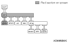
M.U.T.-III SCREEN
|
DIAGNOSIS DETAILS
|
REFERENCE PAGE
|
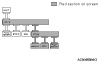
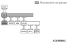
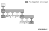
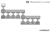
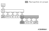
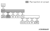
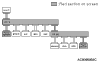
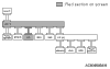
<Comment>
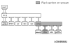
Short circuit to battery in red displayed area is estimated.
|
Diagnosis Item 3
Diagnose the CAN bus lines for short to power supply <Vehicles without A/C and with TCL/ASC system>
|
|
<Comment>
Grounding in red displayed area is estimated.
|
Diagnosis Item 7
Diagnose the CAN bus lines for short to earth <Vehicles without A/C and with TCL/ASC system>
|
|
<Comment>
Short circuit between CAN_H and CAN_L in red displayed area is estimated.
|
Diagnosis Item 11
Diagnose the lines between CAN_L and CAN_H for short circuit <Vehicles without A/C and with TCL/ASC system>
|
|
<Comment>
Mulfunction of terminating resistance is estimated.
|
Diagnosis Item 13
The terminators resistors at both ends or terminator resistor at one side may be defective
|
|
<Comment>
Disconnection in red displayed area is estimated.
|
Diagnosis Item 14
Diagnose the lines between the joint connectors (CAN1 and CAN2)
|
|
<Comment>
Disconnection in red displayed area is estimated.
|
Diagnosis Item 15
Diagnose the lines from the main bus line to the engine-ECU <M/T> or engine-A-M/T-ECU <Automated manual transmission>.
|
|
<Comment>
Disconnection in red displayed area is estimated.
|
Diagnosis Item 17
Diagnose the lines from the main bus line to the ABS/TCL/ASC-ECU <Vehicles with TCL/ASC system>
|
|
<Comment>
Disconnection in red displayed area is estimated.
|
Diagnosis Item 18
Diagnose the lines from the main bus line to the G and yaw rate sensor <Vehicles with TCL/ASC system>
|
|
<Comment>
Disconnection in red displayed area is estimated.
|
Diagnosis Item 19
Diagnose the lines from the main bus line to the electric power steering-ECU <Vehicles with TCL/ASC system>
|
|
<Comment>
Disconnection in red displayed area is estimated.
|
Diagnosis Item 20
Diagnose the lines from the main bus line to the combination meter
|
|
<Comment>
Disconnection in red displayed area is estimated.
|
Diagnosis Item 21
Diagnose the lines from the main bus line to the ETACS-ECU
|
|
<Comment>
Disconnection in red displayed area is estimated.
|
Diagnosis Item 23
Diagnose the lines from the main bus line to the SRS-ECU
|
|
<Comment>
Disconnection in red displayed area is estimated.
|
Diagnosis Item 24
Diagnose the lines from the main bus line to the steering wheel sensor <Vehicles with TCL/ASC system>
|
|
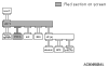
M.U.T.-III SCREEN
|
DIAGNOSIS DETAILS
|
REFERENCE PAGE
|
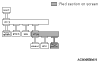
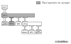
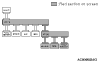
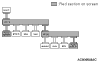
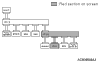
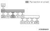
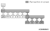
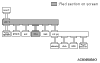
<Comment>
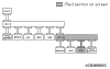
Short circuit to battery in red displayed area is estimated.
|
Diagnosis Item 4
Diagnose the CAN bus lines for short to power supply <Vehicles with A/C and TCL/ASC system>
|
|
<Comment>
Grounding in red displayed area is estimated.
|
Diagnosis Item 8
Diagnose the CAN bus lines for short to earth <Vehicles with A/C and TCL/ASC system>
|
|
<Comment>
Short circuit between CAN_H and CAN_L in red displayed area is estimated.
|
Diagnosis Item 12
Diagnose the lines between CAN_L and CAN_H for short circuit <Vehicles with A/C and TCL/ASC system>
|
|
<Comment>
Malfunction of terminating resistance is estimated.
|
Diagnosis Item 13
The terminators resistors at both ends or terminator resistor at one side may be defective
|
|
<Comment>
Disconnection in red displayed area is estimated.
|
Diagnosis Item 14
Diagnose the lines between the joint connectors (CAN1 and CAN2)
|
|
<Comment>
Disconnection in red displayed area is estimated.
|
Diagnosis Item 15
Diagnose the lines from the main bus line to the engine-ECU <M/T> or engine-A-M/T-ECU <Automated manual transmission>.
|
|
<Comment>
Disconnection in red displayed area is estimated.
|
Diagnosis Item 17
Diagnose the lines from the main bus line to the ABS/TCL/ASC-ECU <Vehicles with TCL/ASC system>
|
|
<Comment>
Disconnection in red displayed area is estimated.
|
Diagnosis Item 18
Diagnose the lines from the main bus line to the G and yaw rate sensor <Vehicles with TCL/ASC system>
|
|
<Comment>
Disconnection in red displayed area is estimated.
|
Diagnosis Item 19
Diagnose the lines from the main bus line to the electric power steering-ECU
|
|
<Comment>
Disconnection in red displayed area is estimated.
|
Diagnosis Item 20
Diagnose the lines from the main bus line to the combination meter
|
|
<Comment>
Disconnection in red displayed area is estimated.
|
Diagnosis Item 21
Diagnose the lines from the main bus line to the ETACS-ECU
|
|
<Comment>
Disconnection in red displayed area is estimated.
|
Diagnosis Item 22
Diagnose the lines from the main bus line to the A/C-ECU <Vehicles with A/C>
|
|
<Comment>
Disconnection in red displayed area is estimated.
|
Diagnosis Item 23
Diagnose the lines from the main bus line to the SRS-ECU
|
|
<Comment>
Disconnection in red displayed area is estimated.
|
Diagnosis Item 24
Diagnose the lines from the main bus line to the steering wheel sensor <Vehicles with TCL/ASC system>
|
|
)
)
)
)
)
)
)
)
)
)
)
)
)
)
)
)
)
)
)
)
)
)
)
)
)
)
)
)
)
)
)
)
)
)
)
)
)
)
)
)
)
)