Inspection Procedure
2: When the engine is started by the Auto Stop & Go (AS&G) System, the sound of
the radio with CD player is interrupted.

|
|
COMMENT ON TROUBLE SYMPTOM
|
|
|
The communication circuit between the capacitor unit and engine-ECU, the capacitor unit,
or the engine-ECU may be faulty. Or due to insufficient charging of the capacitor unit, the voltage
during discharge may be inadequate.
|
|
|
| note |
- The capacitor unit is charged when the ignition switch is in the "ACC" or "ON" position.
- The capacitor unit gradually discharges the electricity in the ignition "OFF" position.
|
|
|
|
- Damaged wiring harness or connector.
- Malfunction of the engine-ECU.
- Malfunction of the capacitor unit.
|
|
|
STEP 1. M.U.T.-III actuator test
|
|
|
Carry out the actuator test for the engine-ECU, and check for the operation of the discharging
relay in the capacitor unit.
|
|
|
(2)Turn all the electrical equipment to "OFF", and wait for 10 minutes.
|
|
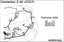
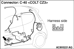
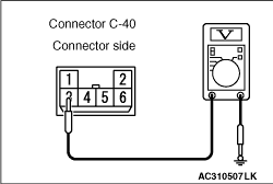
(3)Remove the front seat assembly (left side). With the connector connected, connect the
tester so that the voltage of the capacitor unit connector C-40 (terminal 3) can be measured.
(4)With the radio with CD player "ON", turn the radio on or play a CD for sound output.
(5)Using M.U.T.-III, carry out the actuator test for the engine-ECU, and switch the
capacitor unit into discharge.
(6)Check whether the voltage of the capacitor unit connector C-40 (terminal 3) drops
several seconds later from the battery voltage before the actuator test of the engine-ECU.
Q.
Is the check result normal?
 The charging of the capacitor unit is insufficient. Check the trouble symptom
again. The charging of the capacitor unit is insufficient. Check the trouble symptom
again.
 Go to Step 2. Go to Step 2.
|
|
|
STEP 2. M.U.T.-III actuator test
|
|
|
Carry out the actuator test of the engine-ECU, and check for the engine-ECU connector
whether the engine-ECU sends the switch signal for discharge to the capacitor unit.
|
|
(2)To measure the voltage of the engine-ECU, refer to the actuator test reference table and
prepare the tester. (Refer to GROUP 13A - Troubleshooting, Actuator Test Reference Table  <1100> or
GROUP 13B - Troubleshooting, Actuator Test Reference Table <1300>) <1100> or
GROUP 13B - Troubleshooting, Actuator Test Reference Table <1300>)
(3)Using M.U.T.-III, carry out the actuator test for the engine-ECU, and switch the
capacitor unit into discharge.
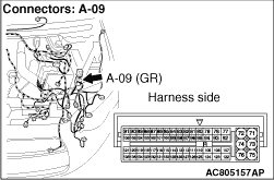
(4)Check if the battery voltage of the engine-ECU A-09 (terminal 135) drastically
drops when the Item 14:Capacitor relay is selected for the actuator test of the engine-ECU. (Refer
to GROUP 13A - Troubleshooting, Check at the Engine-ECU <1100> or
Refer to GROUP 13B - Troubleshooting, Check at the Engine-ECU <1300>)
Q.
Is the check result normal?
Go to Step 3.
Go to Step 6.
|
|
|
STEP 3. M.U.T.-III actuator test
|
|
|
Carry out the actuator test of the engine-ECU, and check for the capacitor unit connector
whether the engine-ECU sends the switch signal for discharge to the capacitor unit.
|
|
(2)With the connector connected, connect the tester so that the voltage of the capacitor
unit connector C-40 (terminal 5) can be measured.
(3)Using M.U.T.-III, carry out the actuator test for the engine-ECU, and switch the
capacitor unit into discharge.
(4)Check if the battery voltage of the capacitor unit connector C-40 (terminal 5)
drastically drops when the Item 14:Capacitor relay is selected for the actuator test of the engine-ECU.
Q.
Is the check result normal?
Go to Step 4.
Replace the capacitor unit.
|
|
|
STEP 4. Connector check: Capacitor unit connector C-40, engine-ECU
connector A-09.
|
|
Q.
Are capacitor unit connector C-40 and engine-ECU connector A-09 connector in good
condition?
Go to Step 5.
Repair or replace the damage component(s).
|
|
|
STEP 5. Check the wiring harness between capacitor unit connector
C-40 (terminal 5) and engine-ECU connector A-09 (terminal 135).
|
|
- Check the signal line open circuit and short circuit.
|
|
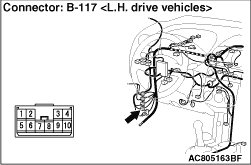
| note |
Prior to the wiring harness inspection, check intermediate connector B-117, and repair
if necessary.
|
Q.
Are the wiring harnesses between capacitor unit connector C-40 (terminal 5) and engine-ECU
connector A-09 (terminal 135) in good condition?
Go to Step 6.
Repair the wiring harness.
|
|
|
STEP 6. Retest the system
|
|
|
(2)Turn all the electrical equipment to "OFF", and wait for 10 minutes.
|
|
|
(3)With the radio with CD player "ON", turn the radio on or play a CD for sound output.
|
|
|
(4)When the engine is started by the Auto Stop & Go System, check if the
sound of the radio with CD player is interrupted.
|
|
|
Q.
Is the check result normal?
|
|
|
This diagnosis is complete.
|
|
|
|
|
|
Replace the Engine-ECU.
|
|
|
|
)
)
)
)
)
)