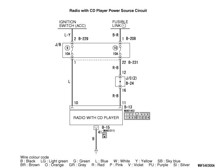
Inspection Procedure 1: When power switch is turned "ON," no power is available. <Vehicle without AS&G System>
|
|
COMMENT ON TROUBLE SYMPTOM
|
|
|
The cause is probably a faulty radio with CD player power supply circuit system.
|
|
|
- Damaged wiring harness or connector.
- Malfunction of the radio with CD player.
|
|
|
STEP 1. Check to see that the power turns ON when the power switch is turned ON.
|
|
|
(1)Turn the ignition switch to "ACC" position.
|
|
|
(2)Turn ON the radio with CD player power switch.
|
|
|
Q.
Is it possible to put the radio with CD player power in the "ON" position?
|
|
|
 Go to Step 9. Go to Step 9.
|
|
|
|
|
|
 Go to Step 2. Go to Step 2.
|
|
|
|
|
|
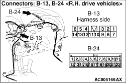
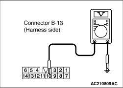
STEP 2. Measure the voltage at radio with CD player connector B-13 (terminal 11) in order to check the battery circuit of power supply system to the radio with CD player.
|
|
(1)Disconnect radio with CD player connector B-13, and measure at the wiring harness side.
|

|
(2)Measure the voltage between terminal 11 and earth.
OK: System voltage
Q.
Is the check result normal?
Go to Step 5.
Go to Step 3.
|
|
|
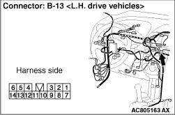
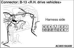
STEP 3. Connector check: radio with CD player connector B-13.
|
|
Q.
Is radio with CD player connector B-13 in good condition?
Go to Step 4.
Repair or replace the damage component(s). If the power switch is turned on, the radio with CD player should operate normally.
|
|
|
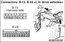
STEP 4. Check the wiring harness between radio with CD player connector B-13 (terminal 11) and FUSIBLE LIMK 1.
|
|
- Check the power supply line (battery power supply) for open circuit and short circuit.
|
|
| note |
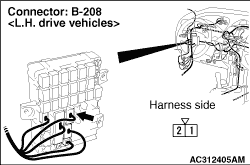
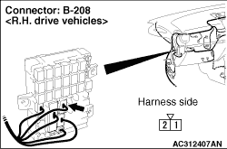
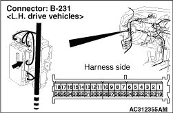
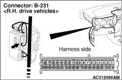
Prior to the wiring harness inspection, check junction block connector B-208 and B-231, and jumper connector B-24, and repair if necessary.
|
Q.
Are the wiring harnesses between radio with CD player connector B-13 (terminal 11) and FUSIBLE LIMK 1 in good condition?
Go to Step 5.
Repair or replace the damage component(s). If the power switch is turned on, the radio with CD player should operate normally.
|
|
|
STEP 5. Measure the voltage at radio with CD player connector B-13 (terminal 10) in order to check the power supply circuit to the radio with CD player (ignition switch ACC).
|
|
(1)Disconnect radio with CD player connector B-13, and measure at the wiring harness side.
(2)Turn the ignition switch to "ACC" position.
|
|
(3)Measure the voltage between terminal 10 and earth.
OK: System voltage
Q.
Is the check result normal?
Go to Step 8.
Go to Step 6.
|
|
|
STEP 6. Connect check: radio with CD player connector B-13.
|
|
Q.
Is radio with CD player connector B-13 in good condition?
Go to Step 7.
Repair or replace the damage component(s).
|
|
|
STEP 7. Check the wiring harness between radio with CD player connector B-13 (terminal 10) and ignition switch (ACC).
|
|
- Check the power supply line (battery power supply) for open circuit and short circuit.
|
|
| note |
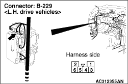
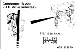
Prior to the wiring harness inspection, check junction block connectors B-229, B-231and repair if necessary.
|
Q.
Is the wiring harness between radio with CD player connector B-13 (terminal 10) and ignition switch (ACC) in good condition?
Troubleshoot the ignition switch. Refer to  . .
Repair or replace the damage component(s).
|
|
|
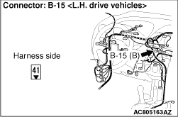
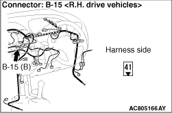
STEP 8. Check the wiring harness between radio with CD player connector B-15 (terminal 41) and earth.
|
|
- Check the earth line for open circuit.
Q.
Are the wiring harnesses between radio with CD player connector B-15 (terminal 41) and earth in good condition?
Go to Step 9.
Repair or replace the damage component(s). If the power switch is turned on, the radio with CD player should operate normally.
|
|
|
STEP 9. Retest the system.
|
|
|
(1)Turn the ignition switch to "ACC" position.
|
|
|
(2)Turn ON the radio with CD player power switch.
|
|
|
Q.
Is it possible to put the radio with CD player power in the "ON" position?
|
|
|
The trouble can be an intermittent malfunction (Refer to GROUP 00, How to Cope with Intermittent Malfunction ).
|
|
|
|
|
|
Replace the radio with CD player.
|
|
|
|
)
)
)
)
)
)
)
)
)
)
)
)
)
)
)