Code No.B1476: IG1 Power supply circuit system (Fuse No.40 circuit)
Code No.B1477: IG1 power supply circuit system (Fuse No.37 circuit)
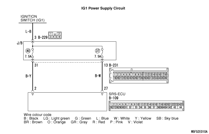
OPERATION
- The SRS-ECU is powered from the ignition switch (IG1).
- The SRS-ECU power is supplied from two circuits. Even if one circuit is shut off, the air bag can inflate.
DIAGNOSIS CODE SET CONDITIONS
This diagnosis code is set if the voltage between the IG1 terminals (fuse No.37 circuit or fuse No.40 circuit) and earth is lower than a predetermined value for a continuous period of five second or more.
PROBABLE CAUSES
- Damaged wiring harnesses or connectors
- Malfunction of the SRS-ECU
|
|
STEP 1. M.U.T.-III CAN bus diagnostics.
|
|
|
| warning |
Since the radiator fan rotates during CAN bus line diagnostics, make sure that no one is servicing the engine compartment before diagnosing the CAN bus line. Since the CAN communication stops when diagnosing the CAN bus line, the ETACS-ECU detects the time-out of the engine-ECU, and activates the radiator fan to prevent overheating as fail-safe.
|
|
|
|
Use the M.U.T.-III to check the CAN bus lines.
|
|
|
Q.
Is the CAN bus line found to be normal?
|
|
|
 Go to Step 2. Go to Step 2.
|
|
|
|
|
|
 Repair the CAN bus line (Refer to GROUP 54C, Troubleshooting - Can Bus Diagnosis Table Repair the CAN bus line (Refer to GROUP 54C, Troubleshooting - Can Bus Diagnosis Table  ). ).
|
|
|
|
|
|
STEP 2.Check whether the diagnosis code is reset.
|
|
|
Check again if the diagnosis code is set.
|
|
|
(1)Erase the diagnosis code.
|
|
|
(2)Turn the ignition switch to "ON" position.
|
|
|
(3)Check if the diagnosis code is set.
|
|
|
(4)Turn the ignition switch to the "LOCK" (OFF) position.
|
|
|
Q.
Is the diagnosis code set?
|
|
|
Go to Step 3.
|
|
|
|
|
|
There is an intermittent malfunction such as poor engaged connector(s) or open circuit (Refer to GROUP 00, How to Cope with Intermittent Malfunction ).
|
|
|
|
|
|
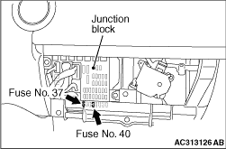
STEP 3. Check junction block fuse number 40 (diagnosis code B1476) or 37 (diagnosis code B1477).
|
|
|
Q.
Is the fuse burned out?
|
|
Go to Step 5.
Go to Step 4.
|
|
|
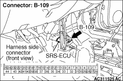
STEP 4. Voltage measurement at the SRS-ECU connector B-109.
|
|
|
(1)Disconnect the negative battery terminal.
|
|
(2)Disconnect SRS-ECU connector B-109.
(3)Connect the negative battery terminal.
(4)Turn the ignition switch to the "ON" position.
|
|
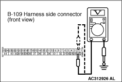
(5)Voltage measurement between B-109 harness side connector terminal 2 (diagnosis code B1476) or 27 (diagnosis code B1477) and body earth.
OK: 9 V or more
Q.
Is the check result normal?
Go to Step 7.
Repair the harness wires between SRS-ECU connector B-109 {terminal No.2 (diagnosis code B1476) or terminal No.27 (diagnosis code B1477)} and ignition switch (IG1).
|
|
|
STEP 5. Check a burned-out fuse.
|
|
|
(2)Turn the ignition switch to the "ON" position, wait for at least one minute and then turn the ignition switch to the "LOCK" (OFF) position.
|
|
|
Q.
Is the fuse in good condition?
|
|
|
Go to Step 7.
|
|
|
|
|
|
Go to Step 6.
|
|
|
|
|
|
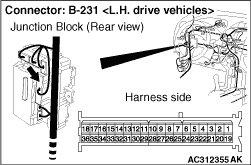
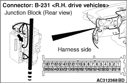
STEP 6. Resistance measurement at the junction block connector B-231.
|
|
(1)Disconnect SRS-ECU connector B-109.
|
|
(2)Disconnect junction block connector B-231, and measure at the wiring harness side.
|
|
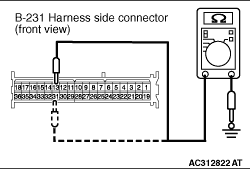
(3)
| caution |
Do not insert a test probe into the terminal from its front side directly, as the connector contact pressure may be weakened.
|
Check for continuity between terminal 31 (diagnosis code B1476) or 13 (diagnosis code B1477) and body earth.
OK: Open circuit
Q.
Is the check result normal?
Check the other circuit, which flows through fuse No.40 (diagnosis code B1476) or fuse No.37 (diagnosis code B1477).
Repair the wiring harness between junction block connector B-231 (terminal No.13, 31) and SRS-ECU connector B-109 (terminal No.27, 2), and replace the fuse.
|
|
|
STEP 7. Check whether the diagnosis code is reset.
|
|
|
Q.
Is diagnosis code B1476 or diagnosis code B1477 set?
|
|
|
Replace the SRS-ECU (Refer to ).
|
|
|
|
|
|
An intermittent malfunction is suspected (Refer to GROUP 00, How to Cope with Intermittent Malfunction ).
|
|
|
|
)
)
)
)
)
)
)