Code No.B1400: Driver’s air bag module (squib) system (short -circuited between terminals of the squib circuit)
| caution |
If diagnosis code B1400 is set in the SRS-ECU, always diagnose the CAN bus lines.
|
OPERATION
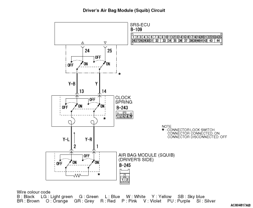
- The SRS-ECU judges how severe a collision is by detecting signals from the front air bag analogue G-sensor. If the impact is over a predetermined level, the SRS-ECU sends an ignition signal. At this time, if the front air bag safing G-sensor is on, the SRS air bag will inflate.
- The ignition signal is input to the air bag module via the clock spring to inflate the air bag.
DIAGNOSIS CODE SET CONDITIONS
- This diagnosis code is set if there is abnormal resistance between the input terminals of the driver’s side air bag module (squib). The most likely causes for this code to be set are the followings:
- Short circuit in driver’s air bag module (squib) or harness
- Short circuit in the clock spring
PROBABLE CAUSES
- Improper engaged connector or defective short spring*
- Short circuit in the clock spring
- Short circuit between the driver’s air bag module (squib) circuit terminals
- Damaged connector(s)
- Malfunction of the SRS-ECU
| note |
*: The squib circuit connectors integrate a "short" spring (which prevents the air bag from deploying unintentionally due to static electricity by shorting the positive wire to the earth wire in the squib circuit when the connectors are disconnected). (Refer to  ). Therefore, if connector B-109, B-243 or B-245 is damaged or improperly engaged, the short spring may not be released when the connector is connected. ). Therefore, if connector B-109, B-243 or B-245 is damaged or improperly engaged, the short spring may not be released when the connector is connected.
|
|
|
STEP 1. M.U.T.-III CAN bus diagnostics
|
|
|
| warning |
Since the radiator fan rotates during CAN bus line diagnostics, make sure that no one is servicing the engine compartment before diagnosing the CAN bus line. Since the CAN communication stops when diagnosing the CAN bus line, the ETACS-ECU detects the time-out of the engine-ECU, and activates the radiator fan to prevent overheating as fail-safe.
|
|
|
|
Use the M.U.T.-III to check the CAN bus lines.
|
|
|
Q.
Is the CAN bus line found to be normal?
|
|
|
 Go to Step 2. Go to Step 2.
|
|
|
|
|
|
 Repair the CAN bus line (Refer to GROUP 54C, Troubleshooting - Can Bus Diagnosis Table ). Repair the CAN bus line (Refer to GROUP 54C, Troubleshooting - Can Bus Diagnosis Table ).
|
|
|
|
|
|
STEP 2. Check whether the diagnosis code is reset.
|
|
|
Check again if the diagnosis code is set.
|
|
|
(1)Erase the diagnosis code.
|
|
|
(2)Turn the ignition switch to "ON" position.
|
|
|
(3)Check if the diagnosis code is set.
|
|
|
(4)Turn the ignition switch to the "LOCK" (OFF) position.
|
|
|
Q.
Is the diagnosis code B1400 set?
|
|
|
Go to Step 3.
|
|
|
|
|
|
There is an intermittent malfunction such as poor engaged connector(s) or open circuit (Refer to GROUP 00, How to Cope with Intermittent Malfunction ).
|
|
|
|
|
|
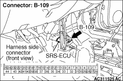
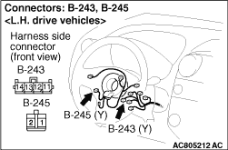
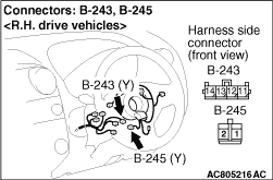
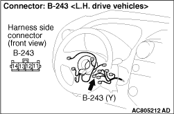
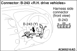
STEP 3. Check SRS-ECU connector B-109, clock spring connector B-243 and driver’s air bag module connector B-245 (M.U.T.-III diagnosis code).
|
|
|
(1)Disconnect the negative battery terminal.
|
|
(2)Disconnect connectors B-109, B-243 and B-245, and then reconnect them.
(3)Connect the negative battery terminal.
(4)Erase the diagnosis code memory, and check the diagnosis code.
Q.
Is diagnosis code B1400 set?
Go to Step 4.
The procedure is complete. It is assumed that diagnosis code B1400 set because connector B-109, B-243 or B-245 was engaged improperly.
|
|
|
STEP 4. Check the driver’s air bag module (M.U.T.-III diagnosis code).
|
|
|
(1)Disconnect the negative battery terminal.
|
|
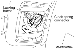
(2)Disconnect the clock spring connector while compressing its locking button and sliding it to the direction of an arrow.
|
|
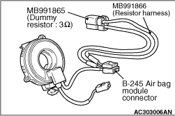
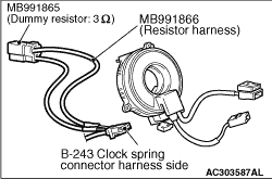
(3)Connect special tool dummy resistor (MB991865) to special tool resistor harness (MB991866).
(4)Insert special tool resistor harness (MB991866) into clock spring side of driver’s air bag module connector B-245.
(5)Connect the negative battery terminal.
(6)Erase the diagnosis code memory, and check the diagnosis code.
Q.
Is diagnosis code B1400 set?
Go to Step 5.
Replace the driver’s air bag module (Refer to ).
|
|
|
STEP 5. Check the clock spring (M.U.T.-III diagnosis code).
|
|
|
(1)Disconnect the negative battery terminal.
|
|
(2)Disconnect the clock spring connector B-243.
|
|
(3)Connect special tool dummy resistor (MB991865) to special tool resistor harness (MB991866).
(4)
| caution |
Do not insert a test probe into the terminal from its front side directly, as the connector contact pressure may be weakened.
|
Insert special tool resistor harness (MB991866) into clock spring harness side connector B-243 (terminal No.13 and 14) by backprobing.
(5)Connect the negative battery terminal.
(6)Erase the diagnosis code memory, and check the diagnosis code.
Q.
Is diagnosis code B1400 set?
Go to Step 6.
Replace the clock spring (Refer to ).
|
|
|
STEP 6. Resistance measurement at the SRS-ECU connector B-109.
|
|
|
(1)Disconnect the negative battery terminal.
|
|
(2)Disconnect SRS-ECU connector B-109.
|
|
(3)
| danger |
To prevent the air bag from deploying unintentionally, disconnect clock spring connector B-243 to short the squib circuit.
|
Disconnect clock spring connector B-243.
|
|
(4)
| caution |
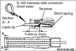
Insert an insulator such as a cable tie to a depth of 4mm or more, otherwise the short spring will not be released.
|
Insert a cable tie [3 mm wide, 0.5 mm thick] between terminals 44 and the short spring to release the short spring.
|
|
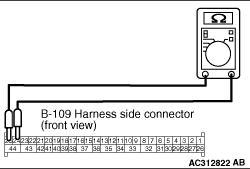
(5)Resistance measurement between B-109 harness side connector terminals 24 and 25.
OK: Open circuit
Q.
Is the check result normal?
Go to Step 7.
Repair the harness wires between SRS-ECU connector B-109 (terminal No.24 and 25) and clock spring connector B-243 (terminal No.13 and 14).
|
|
|
STEP 7. Check whether the diagnosis code is reset.
|
|
|
Q.
Is diagnosis code B1400 set?
|
|
|
Replace the SRS-ECU (Refer to ).
|
|
|
|
|
|
An intermittent malfunction is suspected (Refer to GROUP 00, How to Cope with Intermittent Malfunction ).
|
|
|
|
)
)
)
)
)
)
)
)
)
)
)