|
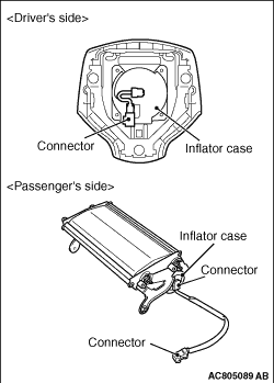
1.Check the pad cover for dents, cracks or deformation.
2.Check the connectors for damage, the terminals for deformation, and the harness for binds.
3.Check the air bag inflator case for dents, cracks or deformation.
4.Install the driver’s air bag module to the steering wheel and check fit and alignment with the wheel.
5.Install the passenger’s (front) air bag module to the instrument panel and front deck crossmember and check fit and alignment.
|
|
|
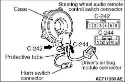
If any malfunction is found in the following inspections, replace the clock spring with a new one.
|
|
1.Check the connectors and protective tubes for damage and the terminal for deformation.
2.Check the case for damage.
3.Check that the continuity exists between the following connector terminals.
- C-242 connector terminal 1 and horn switch connector
- C-242 connector terminal 2 and C-244 connector terminal 5
- C-242 connector terminal 3 and C-244 connector terminal 4
- C-242 connector terminal 4 and C-244 connector terminal 3
- C-242 connector terminal 5 and C-244 connector terminal 2
- C-242 connector terminal 6 and C-244 connector terminal 1
|
|
4.
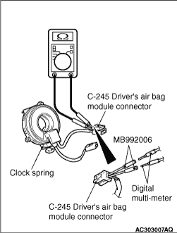
| caution |
Do not directly insert a probe, etc. into the terminal from the front of the connector.
|
Insert the special tool extra fine probe (MB992006) from behind the C-245 driver’s air bag module connector.
5.As shown in the Figure, connect the circuit tester to the special tool extra fine probe (MB992006) and check to see that there is a continuity between the terminals.
|
)
)
)
