|
|
Use M.U.T.-III to diagnose the CAN bus lines.
|
|
|
Q.
Is the check result normal?
|
|
|
 Repair the CAN bus lines (refer to Group 54C, Troubleshooting Repair the CAN bus lines (refer to Group 54C, Troubleshooting  ). ).
|
|
|
|
|
|
(1)Connect the negative battery terminal.
|
|
|
Q.
Does the lamp illuminate?
|
|
|
 Intermittent malfunction (Refer to GROUP 00 - How to Use Troubleshooting/Inspection Service Points - How to Cope with Intermittent Malfunction ). Intermittent malfunction (Refer to GROUP 00 - How to Use Troubleshooting/Inspection Service Points - How to Cope with Intermittent Malfunction ).
|
|
|
|
|
|
(1)Check that the negative battery terminal is disconnected. If connected, disconnect the negative battery terminal.
|
|
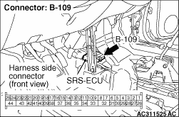
(2)Disconnect SRS-ECU connector B-109.
(3)Connect the negative battery terminal.
(4)Ignition switch: ON
Q.
Does the lamp illuminate?
Replace SRS-ECU (Refer to ).
Go to step 4.
|
|
| note |
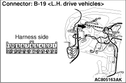
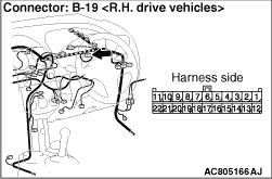
Prior to the wiring harness inspection, check the combination meter connector B-19 and repair if necessary.
|
- The SRS warning lamp inspection for open and short circuit
Q.
Is the check result normal?
Replace the combination meter. (Refer to GROUP 54A, Combination Meter .)
Repair the wiring harness.
|
)
)
)
)