|
|
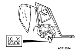
Remove the door trim, and then connect the battery to the door mirror assembly connector to check that the door mirror operates.
|
|
|
|
Battery connection
|
Direction operation
|
- Connect terminal 3 to the negative battery terminal.
- Connect terminal 5 to the positive battery terminal.
|
Up
|
- Connect terminal 3 to the positive battery terminal.
- Connect terminal 5 to the negative battery terminal.
|
Down
|
- Connect terminal 3 to the negative battery terminal.
- Connect terminal 4 to the positive battery terminal.
|
Right
|
- Connect terminal 3 to the positive battery terminal.
- Connect terminal 4 to the negative battery terminal.
|
Left
|
|
|
|
The resistance value between door mirror connector terminals 1 and 2 should meet the standard value with the ambient temperature at a steady 25°C.
Standard value: 9.3 ± 1.0 Ω
|
|
|
|
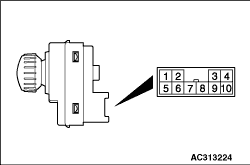
Switch position
|
Tester connection
|
Specified condition
|
OFF
|
8 - 1, 8 - 2, 8 - 6, 8 - 7, 8 - 9, 10 - 1, 10 - 2, 10 - 6, 10 - 7, 10 - 9,
|
Open circuit
|
Left side
|
OFF
|
8 - 2, 8 - 7, 8 - 9, 10 - 2, 10 - 7, 10 - 9
|
Open circuit
|
Up
|
8 - 9, 10 - 2
|
Continuity (Less than 2Ω)
|
Down
|
8 - 2, 10 - 9
|
Right
|
8 - 9, 10 - 7
|
Left
|
8 - 7, 10 - 9
|
Right side
|
OFF
|
8 - 1, 8 - 6, 8 - 9, 10 - 1, 10 - 6, 10 - 9
|
Open circuit
|
Up
|
8 - 9, 10 - 1
|
Continuity (Less than 2Ω)
|
Down
|
8 - 1, 8 - 9
|
Right
|
8 - 9, 10 - 6
|
Left
|
8 - 6, 10 - 9
|
|
|
)
)