|
|
If the power windows do not work at all, the power window relay, the power window main switch or the ETACS-ECU may be defective.
|
|
|
- Malfunction of the power window relay
- Malfunction of the power window main switch
- Malfunction of the ETACS-ECU
- Damaged harness wires and connectors
|
|
|
Check the input signals below, which are related to the lamp reminder buzzer function.
|
|
|
OK: Normal conditions are displayed for all the items.
|
|
|
Q.
Is the check result normal?
|
|
|
 Refer to GROUP 54B, Inspection Procedure J-3 "The ignition switch (IG1) signal is not received Refer to GROUP 54B, Inspection Procedure J-3 "The ignition switch (IG1) signal is not received  ." ."
|
|
|
|
|
Q.
Is the check result normal?
 Go to Step 3. Go to Step 3.
Repair the connector.
|
|
|
Refer to <COLT> or <COLT CZ3>.
|
|
|
Q.
Is the check result normal?
|
|
|
Replace the power window relay.
|
|
|
|
|
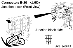
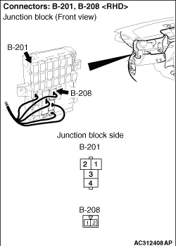
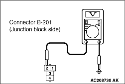
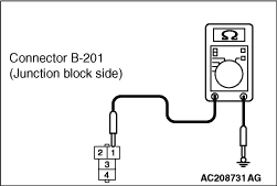
(1)Disconnect the connector, and measure at the junction block side.
(2)Turn the ignition switch to the ON position.
|
|
(3)Check the voltage between the B-201 power window relay connector terminal No.3 and body earth.
OK: System voltage
Q.
Is the check result normal?
Go to Step 6.
Go to Step 5.
|
|
| note |
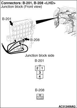
Prior to the wiring harness inspection, check junction block connector B-208, and repair if necessary.
|
- Check the power supply line for open circuit.
Q.
Is the check result normal?
The trouble can be an intermittent malfunction (Refer to GROUP 00, How to use Troubleshooting/inspection Service Points - How to Cope with Intermittent Malfunction ).
Repair the wiring harness.
|
|
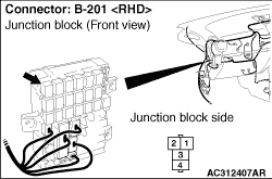
(1)Disconnect the connector, and measure at the junction block side.
(2)Turn the ignition switch to the ON position.
|
|
(3)Check the voltage between the B-201 power window relay connector terminal No.2 and body earth.
OK: System voltage
Q.
Is the check result normal?
Go to Step 9.
Go to Step 7.
|
|
Q.
Is the check result normal?
Go to Step 8.
Repair the connector.
|
|
| note |
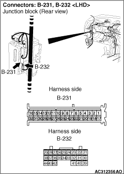
Prior to the wiring harness inspection, check junction block connector B-231, and repair if necessary.
|
- Check the power supply line for open circuit.
Q.
Is the check result normal?
The trouble can be an intermittent malfunction (Refer to GROUP 00, How to use Troubleshooting/inspection Service Points - How to Cope with Intermittent Malfunction ).
Repair the wiring harness.
|
|
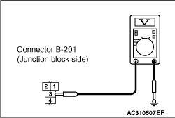
(1)Disconnect the connector, and measure at the junction block side.
|
|
(2)Continuity between B-201 power window relay connector terminal No.1 and body earth
OK: Continuity (Less than 2 Ω)
Q.
Is the check result normal?
Go to Step 11.
Go to Step 10.
|
|
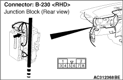
| note |
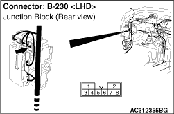
Prior to the wiring harness inspection, check junction block connector B-230, and repair if necessary.
|
- Check the earth wires for open circuit.
Q.
Is the check result normal?
The trouble can be an intermittent malfunction (Refer to GROUP 00, How to use Troubleshooting/inspection Service Points - How to Cope with Intermittent Malfunction ).
Repair the wiring harness.
|
|
Q.
Is the check result normal?
Go to Step 12.
Repair the connector.
|
|
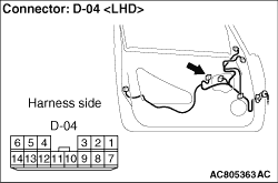
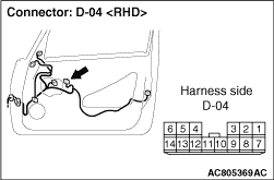
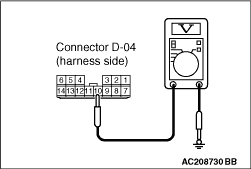
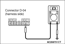
(1)Disconnect the connector, and measure at the wiring harness side.
(2)Turn the ignition switch to the ON position.
|
|
(3)Check the voltage between the D-04 power window main switch connector terminal No.10 and body earth.
OK: System voltage
Q.
Is the check result normal?
Go to Step 14.
Go to Step 13.
|
|
| note |
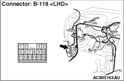
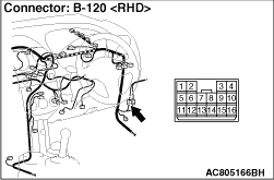
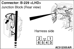
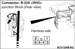
Prior to the wiring harness inspection, check intermediate connector B-119 <LH drive vehicles>, B-120 <RH drive vehicles> and junction block connector B-229, and repair if necessary.
|
- Check the power supply line for open circuit.
Q.
Is the check result normal?
The trouble can be an intermittent malfunction (Refer to GROUP 00, How to use Troubleshooting/inspection Service Points - How to Cope with Intermittent Malfunction ).
Repair the harness wire.
|
|
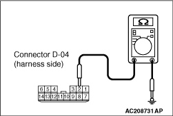
(1)Disconnect the connector, and measure at the wiring harness side.
|
|
(2)Check the resistance between D-04 power window main switch connector terminal No.8 and body earth. <LH drive vehicles>
OK: Continuity (Less than 2 Ω)
|
|
(3)Check the resistance between D-04 power window main switch connector terminal No.2 and body earth. <RH drive vehicles>
OK: Continuity (Less than 2 Ω)
Q.
Is the check result normal?
Go to Step 16.
Go to Step 15.
|
|
| note |
Prior to the wiring harness inspection, check intermediate connector B-119 <LH drive vehicles>, B-120 <RH drive vehicles> and repair if necessary.
|
- Check the earth wires for open circuit.
Q.
Is the check result normal?
The trouble can be an intermittent malfunction (Refer to GROUP 00, How to use Troubleshooting/inspection Service Points - How to Cope with Intermittent Malfunction ).
Repair the wiring harness.
|
|
|
(1)Replace the power window main switch.
|
|
|
(2)Check that the all the power windows work normally.
|
|
|
Q.
Is the check result normal?
|
|
|
The trouble can be an intermittent malfunction (Refer to GROUP 00, How to use Troubleshooting/inspection Service Points - How to Cope with Intermittent Malfunction ).
|
|
|
|
|
|
Replace the ETACS-ECU. Then perform the variant coding (Refer to GROUP 00, Precautions Before Service - How to Perform Variant Coding ).
|
|
|
|
)
)
)
)
)
)
)
)
)
)
)
)
)
)
)
)
)
)
)
)
)
)
)