|
|
- The torque sensor power supply monitor voltage does not meet a predetermined
voltage stored in the microcomputer, and the microcomputer determines that there is a problem
in the torque power supply voltage.
Criteria for judging malfunction
- The 8-V power supply voltage is more than 8.5 V or less than 7.5 V, or the 3-V power
supply voltage is more than 3.12 V or less than 2.88 V.
|
|
|
- Defective harness wire(s) or connector(s)
- Defective torque sensor of the steering gear and linkage assembly
- The EPS-ECU is defective.
|
|
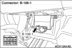
Q.
Is any wire between electric power steering-ECU connector B-106-1 (terminals 13 to
14 and 18) and torque sensor damaged?
 Repair the harness connector and terminal, or replace the steering gear box and
linkage assembly (Refer to Repair the harness connector and terminal, or replace the steering gear box and
linkage assembly (Refer to  ). ).
 Go to Step 2. Go to Step 2.
|
|
Disconnect electric power steering-ECU connector B-106-1, and measure the internal resistance
in the ECU.
- Measure the resistance between connector B-106-1 terminals 13 and 18.
OK: 400 - 800 Ω
Q.
Is the check result normal?
Go to Step 3.
Replace the electric power steering-ECU.
|
|
Disconnect electric power steering-ECU connector B-106-1, and measure the resistances
between the connector-side terminals of the steering gear box.
- Between connector B-106-1 terminal 18 and body earth
- Between connector B-106-1 terminal 14 and body earth
- Between connector B-106-1 terminals 18 and 13
- Between connector B-106-1 terminals 14 and 13
OK: Open circuit or more than 100 Ω
Q.
Is the check result normal?
Go to Step 4.
Replace the steering gear box and linkage assembly (Refer to ).
|
|
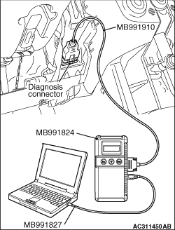
| caution |
Before connecting or disconnecting the M.U.T.-III, turn the ignition switch to the "LOCK"
(OFF) position.
|
Check again if the diagnosis code is set.
(1)Turn the ignition switch to the "ON" position.
(2)Erase the diagnosis code.
(3)Turn the ignition switch to the "LOCK" (OFF) position.
(4)Turn the ignition switch to the "ON" position.
(5)Check if the diagnosis code is set.
(6)Turn the ignition switch to the "LOCK" (OFF) position.
(7)Disconnect M.U.T.-III.
Q.
Is diagnosis code C1514 set?
Replace the electric power steering-ECU (Refer to ).
The malfunction is intermittent. Refer to GROUP 00 - How to Use Troubleshooting/Inspection
Service Points - How to Cope with Intermittent Malfunction .
|
)
)
)