|
|
These diagnosis codes are set in the following case:
|
|
|
C1511: Torque sensor main system malfunction
- The torque sensor main output voltage does not meet a predetermined voltage stored
in the microcomputer, and the microcomputer determines that there is a problem in the torque
sensor main system.
Criteria for judging malfunction
- The torque sensor main output voltage is more than 4.5 V or less than 0.5 V.
|
|
|
C1512: Torque sensor sub system malfunction
- The torque sensor sub output voltage does not meet a predetermined voltage stored
in the microcomputer, and the microcomputer determines that there is a problem in the torque
sensor sub system.
Criteria for judging malfunction
- The torque sensor sub output voltage is more than 4.5 V or less than 0.5 V.
|
|
|
C1511: Torque sensor main system malfunction
- Defective harness wire(s) or connector(s)
- Defective torque sensor of the steering gear and linkage assembly
- Malfunction of the electric power steering-ECU
|
|
|
C1512: Torque sensor sub system malfunction
- Defective harness wire(s) or connector(s)
- Defective torque sensor of the steering gear and linkage assembly
- Malfunction of the electric power steering-ECU
|
|
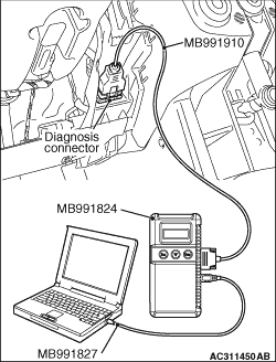
| caution |
Before connecting or disconnecting the M.U.T.-III, turn the ignition switch to the "LOCK"
(OFF) position.
|
Check again if the diagnosis code is set.
(1)Turn the ignition switch to the "ON" position.
(2)Erase the diagnosis code.
(3)Turn the ignition switch to the "LOCK" (OFF) position.
(4)Turn the ignition switch to the "ON" position.
(5)Start the engine, and check the diagnosis code.
(6)Turn the ignition switch to the "LOCK" (OFF) position.
Q.
Is the diagnosis code, which has been set before starting the engine, still set?
 Go to Step 2. Go to Step 2.
 Go to Step 12. Go to Step 12.
|
|
| caution |
Before connecting or disconnecting the M.U.T.-III, turn the ignition switch to the "LOCK"
(OFF) position.
|
Check again if the diagnosis code is set.
(1)Turn the ignition switch to the "ON" position.
(2)Erase the diagnosis code.
(3)Turn the ignition switch to the "LOCK" (OFF) position.
(4)Turn the ignition switch to the "ON" position.
(5)Check whether diagnosis codes C1511 and C1512 are set simultaneously.
(6)Turn the ignition switch to the "LOCK" (OFF) position.
Q.
Are diagnosis codes C1511 and C1512 set simultaneously?
Go to Step 8.
Go to Step 3.
|
|
Q.
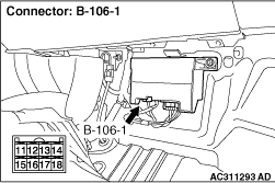
Is any wire between electric power steering-ECU connector B-106-1 (terminals 13 to
12 and 16) and torque sensor damaged?
Repair the harness connector and terminal, or replace the steering gear box and
linkage assembly (Refer to  ). ).
Go to Step 4.
|
|
Use the M.U.T.-III voltage measurement and data list functions to measure the torque sensor
main voltage <C1511> or sub voltage <C1512> before the fail-safe
relay is activated (one second after the engine is started) without disconnecting connector
B-106-1 (by backprobing).
- The steering is in the neutral position.
- Item 01: Torque sensor main system (Refer to ).
- Item 02: Torque sensor sub system (Refer to ).
- Item 03: Torque sensor voltage (Refer to ).
- Measure the voltage between connector B-106-1 terminals 12 and 13 (for main system),
or connector B-106-1 terminals 13 and 16 (for sub system).
OK: 2.4 - 2.6 V
Q.
Is the check result normal?
Go to Step 7.
Go to Step 5.
|
|
Disconnect electric power steering-ECU connector B-106-1, and measure the internal resistance
in the ECU.
- Measure the resistance between connector B-106-1 terminals 12 and 13 (for
main system), or connector B-106-1 terminals 13 and 16 (for sub system).
OK: 0.5 - 1.5 kΩ
Q.
Is the check result normal?
Go to Step 6.
Replace the electric power steering-ECU (Refer to ).
|
|
| caution |
Before connecting or disconnecting the M.U.T.-III, turn the ignition switch to the "LOCK"
(OFF) position.
|
Check again if the diagnosis code is set.
(1)Turn the ignition switch to the "ON" position.
(2)Erase the diagnosis code.
(3)Turn the ignition switch to the "LOCK" (OFF) position.
(4)Turn the ignition switch to the "ON" position.
(5)Check if the diagnosis code is set.
(6)Turn the ignition switch to the "LOCK" (OFF) position.
Q.
Is diagnosis code C1511 or C1512 set?
Replace the steering gear box and linkage assembly (Refer to ).
The malfunction is intermittent. Refer to GROUP 00 - How to Use Troubleshooting/Inspection Service
Points - How to Cope with Intermittent Malfunction .
|
|
| caution |
Before connecting or disconnecting the M.U.T.-III, turn the ignition switch to the "LOCK"
(OFF) position.
|
Check again if the diagnosis code is set.
(1)Turn the ignition switch to the "ON" position.
(2)Erase the diagnosis code.
(3)Turn the ignition switch to the "LOCK" (OFF) position.
(4)Turn the ignition switch to the "ON" position.
(5)Check if the diagnosis code is set.
(6)Turn the ignition switch to the "LOCK" (OFF) position.
Q.
Is diagnosis code C1511 or C1512 set?
Replace the electric power steering-ECU (Refer to ).
The malfunction is intermittent. Refer to GROUP 00 - How to Use Troubleshooting/Inspection Service
Points - How to Cope with Intermittent Malfunction .
|
|
Q.
Is any wire between electric power steering-ECU connector B-106-1 (terminals 13 to
14 and 18) and torque sensor damaged?
Repair the harness connector and terminal, or replace the steering gear box and
linkage assembly (Refer to ).
Go to Step 9.
|
|
Measure the voltage between the 3-V power supply (connector B-106-1 terminal 18) and body
earth without disconnecting the connector (by backprobing).
OK: 2.88 - 3.12 V
Q.
Is the check result normal?
Go to Step 10.
Replace the electric power steering-ECU (Refer to ).
|
|
Measure the 8-V power supply voltage between connector B-106-1 terminal 14 and body earth
without disconnecting the connector (by backprobing).Disconnect electric power steering-ECU,
and measure the internal resistance in the ECU.
- Ignition switch: ON
- Measure the voltage between the 8-V power supply (connector B-106-1 terminal 14)
and the body earth.
OK: 7.5 - 8.5 V
Q.
Is the check result normal?
Go to Step 11.
Replace the electric power steering-ECU (Refer to ).
|
|
| caution |
Before connecting or disconnecting the M.U.T.-III, turn the ignition switch to the "LOCK"
(OFF) position.
|
Check again if the diagnosis code is set.
(1)Turn the ignition switch to the "ON" position.
(2)Erase the diagnosis code.
(3)Turn the ignition switch to the "LOCK" (OFF) position.
(4)Turn the ignition switch to the "ON" position.
(5)Check if the diagnosis code is set.
(6)Turn the ignition switch to the "LOCK" (OFF) position.
Q.
Is diagnosis code C1511 or C1512 set?
Replace the steering gear box and linkage assembly (Refer to ).
The malfunction is intermittent. Refer to GROUP 00 - How to Use Troubleshooting/Inspection Service
Points - How to Cope with Intermittent Malfunction .
|
|
| caution |
Before connecting or disconnecting the M.U.T.-III, turn the ignition switch to the "LOCK"
(OFF) position.
|
Check again if the diagnosis code is set.
(1)Turn the ignition switch to the "ON" position.
(2)Erase the diagnosis code.
(3)Turn the ignition switch to the "LOCK" (OFF) position.
(4)Turn the ignition switch to the "ON" position.
(5)After starting the engine, check whether diagnosis code C1511 or C1512 is set.
(6)Turn the ignition switch to the "LOCK" (OFF) position.
Q.
Is diagnosis code C1511 or C1512 set?
Go to Step 13.
The malfunction is intermittent. Refer to GROUP 00 - How to Use Troubleshooting/Inspection Service
Points - How to Cope with Intermittent Malfunction .
|
|
Q.
Is any wire between electric power steering-ECU connector B-106-1 (terminals 13) and
torque sensor damaged?
Repair the harness connector and terminal, or replace the steering gear box and
linkage assembly (Refer to ).
Go to Step 14.
|
|
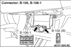
Disconnect electric power steering-ECU connectors B-105 and B-106-1, and measure the internal
resistance in the ECU.
- Measure the resistance between connector B-105 terminal 21 and connector
B-106-1 terminal 13.
OK: Continuity exists (2 Ω or less)
Q.
Is the check result normal?
Replace the electric power steering-ECU (Refer to ).
Go to Step 15.
|
|
| caution |
Before connecting or disconnecting the M.U.T.-III, turn the ignition switch to the "LOCK"
(OFF) position.
|
Check again if the diagnosis code is set.
(1)Turn the ignition switch to the "ON" position.
(2)Erase the diagnosis code.
(3)Turn the ignition switch to the "LOCK" (OFF) position.
(4)Turn the ignition switch to the "ON" position.
(5)After starting the engine, check whether diagnosis code C1511 or C1512 is set.
(6)Turn the ignition switch to the "LOCK" (OFF) position.
(7)Disconnect M.U.T.-III.
Q.
Is diagnosis code C1511 or C1512 set?
Replace the steering gear box and linkage assembly (Refer to ).
The malfunction is intermittent. Refer to GROUP 00 - How to Use Troubleshooting/Inspection Service
Points - How to Cope with Intermittent Malfunction .
|
)
)
)
)